The PWM peripheral clock is divided in the clock generator module to provide different clocks available for all channels. Each channel can independently select one of the divided clocks.
The clock generator is divided into different blocks:
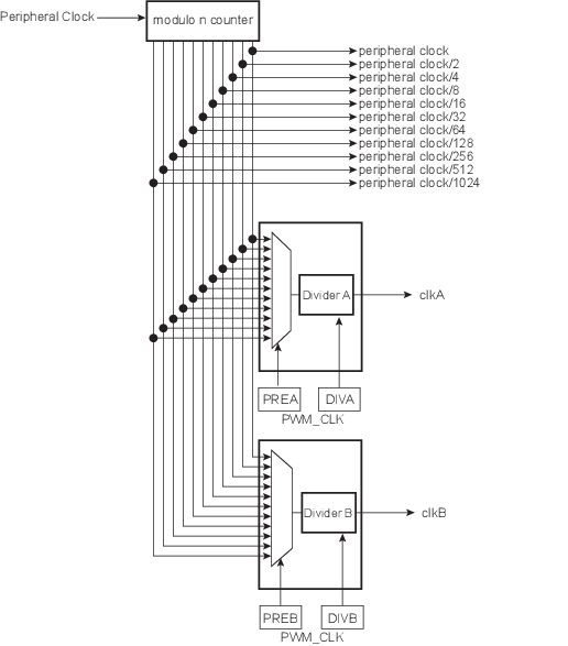
- a modulo n counter which provides 11 clocks: fperipheral clock, fperipheral clock/2, fperipheral clock/4, fperipheral clock/8, fperipheral clock/16, fperipheral clock/32, fperipheral clock/64, fperipheral clock/128, fperipheral clock/256, fperipheral clock/512, fperipheral clock/1024
- two linear dividers (1, 1/2, 1/3, ... 1/255) that provide two separate clocks: clkA and clkB
Each linear divider can independently divide one of the clocks of the modulo n counter. The selection of the clock to be divided is made according to the PREA (PREB) field of the PWM Clock register (PWM_CLK). The resulting clock clkA (clkB) is the clock selected divided by DIVA (DIVB) field value.
After a reset of the PWM controller, DIVA (DIVB) and PREA (PREB) are set to ‘0’. This implies that after reset clkA (clkB) are turned off.
At reset, all clocks provided by the modulo n counter are turned off except the peripheral clock. This situation is also true when the PWM peripheral clock is turned off through the Power Management Controller.