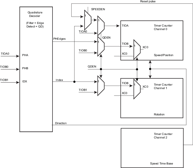
The quadrature decoder (QDEC) is driven by TIOA0, TIOB0 and TIOB1 input pins and drives the timer counter of channel 0 and 1. Channel 2 can be used as a time base in case of speed measurement requirements (refer to Predefined Connection of the Quadrature Decoder with Timer Counters).
When writing a ‘0’ to TC_BMR.QDEN, the QDEC is bypassed and the IO pins are directly routed to the timer counter function.
TIOA0 and TIOB0 are to be driven by the two dedicated quadrature signals from a rotary sensor mounted on the shaft of the off-chip motor.
A third signal from the rotary sensor can be processed through pin TIOB1 and is typically dedicated to be driven by an index signal if it is provided by the sensor. This signal is not required to decode the quadrature signals PHA, PHB.
TC_CMRx.TCCLKS must be configured to select XC0 input (i.e., 0x101). Field TC0XC0S has no effect as soon as the QDEC is enabled.
Either speed or position/revolution can be measured. Position channel 0 accumulates the edges of PHA, PHB input signals giving a high accuracy on motor position whereas channel 1 accumulates the index pulses of the sensor, therefore the number of rotations. Concatenation of both values provides a high level of precision on motion system position.
In Speed mode, position cannot be measured but revolution can be measured.
Inputs from the rotary sensor can be filtered prior to downstream processing. Accommodation of input polarity, phase definition and other factors are configurable.
Interruptions can be generated on different events.
A compare function (using TC_RC) is available on channel 0 (speed/position) or channel 1 (rotation) and can generate an interrupt by means of TC_SRx.CPCS.