The dead-time generator uses the comparator output OCx to provide the two complementary outputs DTOHx and DTOLx, which allows the PWM macrocell to drive external power control switches safely. When the dead-time generator is enabled by setting the bit DTE to 1 or 0 in the PWM Channel Mode Register (PWM_CMRx), dead-times (also called dead-bands or non-overlapping times) are inserted between the edges of the two complementary outputs DTOHx and DTOLx. Note that enabling or disabling the dead-time generator is allowed only if the channel is disabled.
The dead-time is adjustable by the PWM Channel Dead Time Register (PWM_DTx). Each output of the dead-time generator can be adjusted separately by DTH and DTL. The dead-time values can be updated synchronously to the PWM period by using the PWM Channel Dead Time Update Register (PWM_DTUPDx).
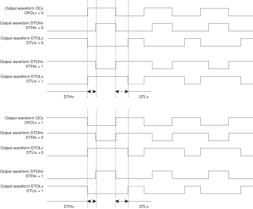
The dead-time is based on a specific counter which uses the same selected clock that feeds the channel counter of the comparator. Depending on the edge and the configuration of the dead-time, DTOHx and DTOLx are delayed until the counter has reached the value defined by DTH or DTL. An inverted configuration bit (DTHI and DTLI bit in PWM_CMRx) is provided for each output to invert the dead-time outputs. The following figure shows the waveform of the dead-time generator.