Four combinations of polarity and phase are available for data transfers. The clock polarity is programmed with the CPOL bit in the QSPI Serial Clock register (QSPI_SCR). The CPHA bit in the QSPI_SCR programs the clock phase. These two parameters determine the edges of the clock signal on which data is driven and sampled. Each of the two parameters has two possible states, resulting in four possible combinations that are incompatible with one another. Thus, the interfaced slave must use the same parameter values to communicate.
The table below shows the four modes and corresponding parameter settings.
| QSPI Clock Mode | QSPI_SCR.CPOL | QSPI_SCR.CPHA | Shift QSCK Edge | Capture QSCK Edge | QSCK Inactive Level |
|---|---|---|---|---|---|
| 0 | 0 | 0 | Falling | Rising | Low |
| 1 | 0 | 1 | Rising | Falling | Low |
| 2 | 1 | 0 | Rising | Falling | High |
| 3 | 1 | 1 | Falling | Rising | High |
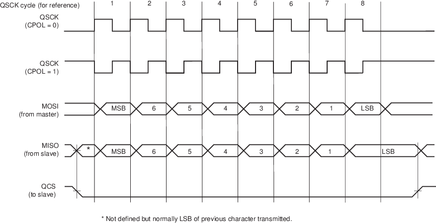
The following figures show examples of data transfers.
Figure 1. QSPI Transfer Format (QSPI_SCR.CPHA = 0, 8 bits per
transfer)
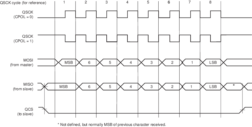
Figure 2. QSPI Transfer Format (QSPI_SCR.CPHA = 1, 8 bits per
transfer)