All waveforms in the following examples describe SPI transfers in SPI Clock mode 0 (QSPI_SCR.CPOL = 0 and QSPI_SCR.CPHA = 0; see section Serial Clock Phase and Polarity).
All system bus accesses described below refer to the system bus address phase. System bus wait cycles and system bus data phases are not shown.
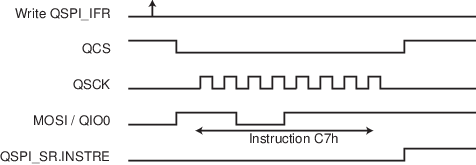
Example 1:
Instruction in Single-bit SPI, without address, without option, without data.
Command: CHIP ERASE (C7h).
- Write 0x0000_00C7 in QSPI_ICR.
- Write 0x0000_0010 in QSPI_IFR.
- Wait for QSPI_SR.INSTRE to rise.
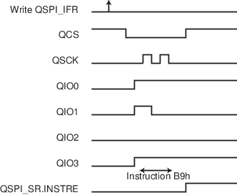
Example 2:
Instruction in Quad SPI, without address, without option, without data.
Command: POWER DOWN (B9h)
- Write 0x0000_00B9 in QSPI_ICR.
- Write 0x0000_0016 in QSPI_IFR.
- Wait for QSPI_SR.INSTRE to rise.
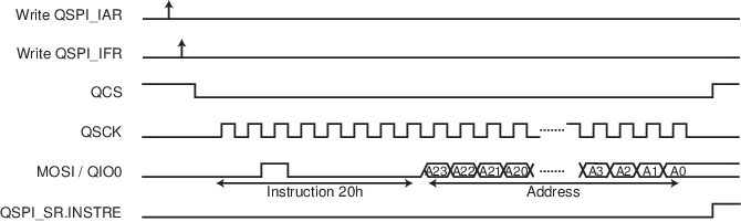
Example 3:
Instruction in Single-bit SPI, with address in Single-bit SPI, without option, without data.
Command: BLOCK ERASE (20h)
- Write the address (of the block to erase) in QSPI_AR.
- Write 0x0000_0020 in QSPI_ICR.
- Write 0x0000_0030 in QSPI_IFR.
- Wait for QSPI_SR.INSTRE to rise.
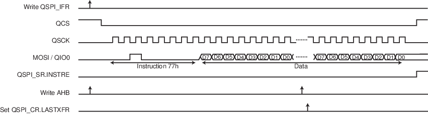
Example 4:
Instruction in Single-bit SPI, without address, without option, with data write in Single-bit SPI.
Command: SET BURST (77h)
- Write 0x0000_0077 in QSPI_ICR.
- Write 0x0000_2090 in QSPI_IFR.
- Read QSPI_IFR (dummy read) to synchronize system bus accesses.
- Write data in the system bus memory space (0x80000000). The address of system bus write accesses is not used.
- Write a ‘1’ to QSPI_CR.LASTXFR.
- Wait for QSPI_SR.INSTRE to rise.Figure 4. Instruction Transmission Waveform 4
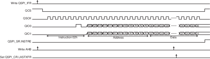
Example 5:
Instruction in Single-bit SPI, with address in Dual SPI, without option, with data write in Dual SPI.
Command: BYTE/PAGE PROGRAM (02h)
- Write 0x0000_0002 in QSPI_ICR.
- Write 0x0000_30B3 in QSPI_IFR.
- Read QSPI_IFR (dummy read) to synchronize system bus accesses.
- Write data in the QSPI system bus memory space (0x80000000). The address of the first system bus write access is sent in the instruction frame. The address of the next system bus write accesses is not used.
- Write a ‘1’ to QSPI_CR.LASTXFR.
- Wait for QSPI_SR.INSTRE to rise.Figure 5. Instruction Transmission Waveform 5
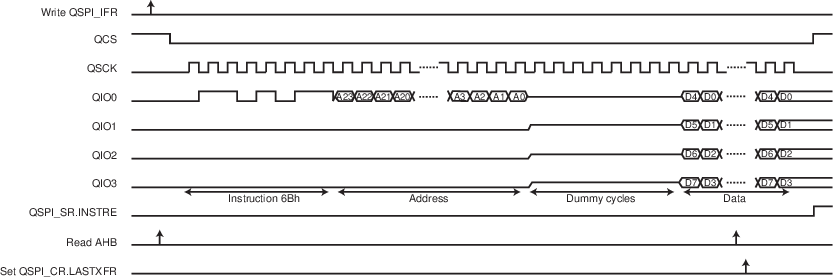
Example 6:
Instruction in Single-bit SPI, with address in Single-bit SPI, without option, with data read in Quad SPI, with eight dummy cycles.
Command: QUAD_OUTPUT READ ARRAY (6Bh)
- Write 0x0000_006B in QSPI_ICR.
- Write 0x0008_10B2 in QSPI_IFR.
- Read QSPI_IR (dummy read) to synchronize system bus accesses.
- Read data in the QSPI system bus memory space (0x80000000). The address of the first system bus read access is sent in the instruction frame. The address of the next system bus read accesses is not used.
- Write a ‘1’ to QSPI_CR.LASTXFR.
- Wait for QSPI_SR.INSTRE to rise.Figure 6. Instruction Transmission Waveform 6
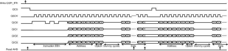
Example 7:
Instruction in Single-bit SPI, with address and option in Quad SPI, with data read in Quad SPI, with four dummy cycles, with fetch and continuous read.
Command: FAST READ QUAD I/O (EBh) - 8-BIT OPTION (0x30h)
- Write 0x0030_00EB in QSPI_ICR.
- Write 0x0004_33F4 in QSPI_IFR.
- Read QSPI_IFR (dummy read) to synchronize system bus accesses.
- Read data in the QSPI system bus memory space (0x80000000). Fetch is enabled, the address of the system bus read accesses is always used.
- Write a ‘1’ to QSPI_CR.LASTXFR.
- Wait for QSPI_SR.INSTRE to rise.Figure 7. Instruction Transmission Waveform 7
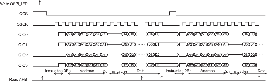
Example 8:
Instruction in Quad SPI, with address in Quad SPI, without option, with data read in Quad SPI, with two dummy cycles, with fetch.
Command: HIGH-SPEED READ (0Bh)
- Write 0x0000_000B in QSPI_ICR.
- Write 0x0002_20B6 in QSPI_IFR.
- Read QSPI_IFR (dummy read) to synchronize system bus accesses.
- Read data in the QSPI system bus memory space (0x80000000). Fetch is enabled, the address of the system bus read accesses is always used.
- Write a ‘1’ to QSPI_CR.LASTXFR.
- Wait for QSPI_SR.INSTRE to rise.Figure 8. Instruction Transmission Waveform 8
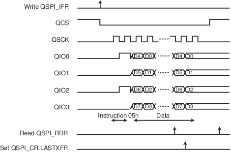
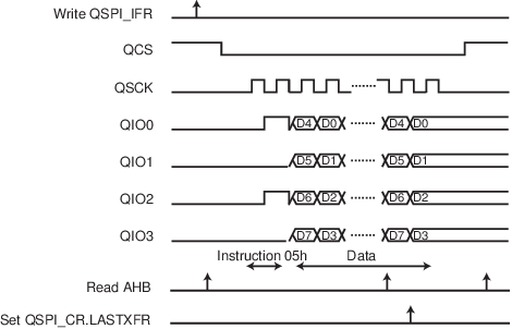
Example 9:
Instruction in Quad SPI, without address, without option, with data read in Quad SPI, without dummy cycles, without fetch.
Command: HIGH-SPEED READ (05h)
- Write 0x0000_0005 in QSPI_ICR.
- Write 0x0000_0096 in QSPI_IFR.
- Read QSPI_IFR (dummy read) to synchronize system bus accesses.
- Read data in the QSPI system bus memory space (0x80000000). Fetch is disabled.
- Write a ‘1’ to QSPI_CR.LASTXFR.
- Wait for QSPI_SR.INSTRE to rise.
Example 10:
Instruction in Quad SPI, without address, without option, with data read in Quad SPI, without dummy cycles, without fetch, read launched through APB interface.
Command: HIGH-SPEED READ (05h)
- Set SMRM to ‘1’ in QSPI_MR
- Write 0x0000_0005 in QSPI_ICR.
- Write 0x0100_0096 in QSPI_IFR (will start the transfer).
- Wait flag RDRF and Read data in the QSPI_RDR register Fetch is disabled.
- Write a ‘1’ to QSPI_CR.LASTXFR.
- Wait for QSPI_SR.INSTRE to rise.