In this mode, the update of the period value, the duty-cycle values, the dead-time values and the update period value must be done by writing in their respective update registers with the processor (respectively PWM_CPRDUPDx, PWM_CDTYUPDx, PWM_DTUPDx and PWM_SCUPUPD).
To trigger the update of the period value and the dead-time values, the user must use the bit UPDULOCK in the PWM_SCUC register, which updates synchronously (at the same PWM period) the synchronous channels:
- If the bit UPDULOCK is set to ‘1’, the update is done at the next PWM period of the synchronous channels.
- If the UPDULOCK bit is not set to ‘1’, the update is locked and cannot be performed.
After writing the UPDULOCK bit to ‘1’, it is held at this value until the update occurs, then it is read 0.
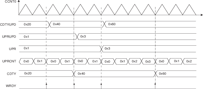
The update of the duty-cycle values and the update period is triggered automatically after an update period.
To configure the automatic update, the user must define a value for the update period by the UPR field in the PWM_SCUP register. The PWM controller waits UPR+1 period of synchronous channels before updating automatically the duty values and the update period value.
The status of the duty-cycle value write is reported in the PWM Interrupt Status Register 2 (PWM_ISR2) by the following flags:
- WRDY: this flag is set to ‘1’ when the PWM Controller is ready to receive new duty-cycle values and a new update period value. It is reset to ‘0’ when the PWM_ISR2 register is read.
Depending on the interrupt mask in the PWM Interrupt Mask Register 2 (PWM_IMR2), an interrupt can be generated by these flags.
Sequence for Method 2:
- 1.Select the manual write of duty-cycle values and the automatic update by setting the field UPDM to ‘1’ in the PWM_SCM register
- 2.Define the synchronous channels by the bits SYNCx in the PWM_SCM register.
- 3.Define the update period by the field UPR in the PWM_SCUP register.
- 4.Enable the synchronous channels by writing CHID0 in the PWM_ENA register.
- 5.If an update of the period value and/or of the dead-time values is required, write registers that need to be updated (PWM_CPRDUPDx, PWM_DTUPDx), else go to Step 8.
- 6.Set UPDULOCK to ‘1’ in PWM_SCUC.
- 7.The update of these registers will occur at the beginning of the next PWM period. At this moment the bit UPDULOCK is reset, go to Step 5. for new values.
- 8.If an update of the duty-cycle values and/or the update period is required, check first that write of new update values is possible by polling the flag WRDY (or by waiting for the corresponding interrupt) in PWM_ISR2.
- 9.Write registers that need to be updated (PWM_CDTYUPDx, PWM_SCUPUPD).
- 10.The update of these registers will occur at the next PWM period
of the synchronous channels when the Update Period is elapsed. Go to Step 8. for new values.Figure 1. Method 2 (UPDM = 1)