At exit from Wait mode, the device allows the processor to restart in several microseconds only if the C-code function that manages the Wait mode entry and exit is linked to and executed from on-chip SRAM.
The fast startup time cannot be achieved if the first instruction after an exit is located in the embedded Flash.
If fast startup is not required, or if the first instruction after exit from Wait mode is located in embedded Flash, see "Startup from Embedded Flash".
To instruct the device to enter Wait mode, refer to section “Power Considerations”.
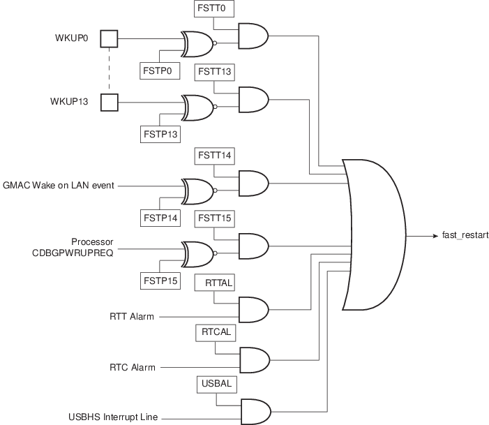
A fast startup occurs upon the detection of a programmed level on one of the 14 wakeup inputs (WKUP) or upon an active alarm from the RTC, RTT and USB Controller. The polarity of each of the 14 wakeup inputs is programmable in the PMC Fast Startup Polarity Register (PMC_FSPR).
The fast startup circuitry, as shown in the following figure, is fully asynchronous and provides a fast startup signal to the PMC. As soon as the fast startup signal is asserted, the Main RC oscillator restarts automatically.
When entering Wait mode, the embedded Flash can be placed in one of the low-power modes (Deep-powerdown or Standby mode) with PMC_FSMR.FLPM. FLPM can be configured at any time and its value will be applied to the next Wait mode period.
The power consumption reduction is optimal when PMC_FSMR.FLPM is configured to ‘1’ (Deep-powerdown mode). If the field is configured to ‘0’ (Standby mode), the power consumption is slightly higher than in Deep-powerdown mode.
When PMC_FSMR.FLPM is configured to ‘2’, the Wait mode Flash power consumption is equivalent to that of the Active mode when there is no read access on the Flash.
Each wakeup input pin and alarm can be enabled to generate a fast startup event by setting the corresponding bit in PMC_FSMR.
The user interface does not provide any status for fast startup. The status can be read in the PIO Controller and the status registers of the RTC, RTTand USB Controller.