In this mode, the update of the period value, the duty-cycle values and the dead-time values must be done by writing in their respective update registers with the processor (respectively PWM_CPRDUPDx, PWM_CDTYUPDx and PWM_DTUPDx).
To trigger the update, the user must use the bit UPDULOCK in the PWM_SCUC register which allows to update synchronously (at the same PWM period) the synchronous channels:
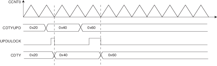
- If the bit UPDULOCK is set to ‘1’, the update is done at the next PWM period of the synchronous channels.
- If the UPDULOCK bit is not set to ‘1’, the update is locked and cannot be performed.
After writing the UPDULOCK bit to ‘1’, it is held at this value until the update occurs, then it is read 0.
Sequence for Method 1:
- 1.Select the manual write of duty-cycle values and the manual update by setting the UPDM field to ‘0’ in the PWM_SCM register.
- 2.Define the synchronous channels by the SYNCx bits in the PWM_SCM register.
- 3.Enable the synchronous channels by writing CHID0 in the PWM_ENA register.
- 4.If an update of the period value and/or the duty-cycle values and/or the dead-time values is required, write registers that need to be updated (PWM_CPRDUPDx, PWM_CDTYUPDx and PWM_DTUPDx).
- 5.Set UPDULOCK to ‘1’ in PWM_SCUC.
- 6.The update of the registers will occur at the beginning of the
next PWM period. When the UPDULOCK bit is reset, go to Step 4. for new values.Figure 1. Method 1 (UPDM = 0)