The source of the UTMI PLL (UPLL) is the Main Crystal oscillator. The UPLL provides the UTMI PLL Clock (UPLLCK) and UPLLCKDIV clock signals.
The UPLL has two possible multiplying factors: x40 and x30. To generate UPLLCK at 480 MHz (typical USB case), this leads to two possible crystal oscillator frequencies: 12 or 16 MHz. The crystal oscillator frequency (12 or 16 MHz) must be programmed in UTMI_CKTRIM.FREQ prior to enabling the UPLL.
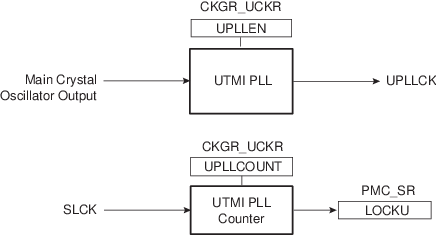
When the UPLL is enabled by writing a ‘1’ to bit UPLLEN in the UTMI Clock Register (CKGR_UCKR), the LOCKU bit in PMC_SR is automatically cleared. The values written in the PLLCOUNT field in CKGR_UCKR are loaded in the UTMI PLL counter. The UTMI PLL counter then decrements at the speed of SLCK divided by 8 until it reaches ‘0’. At this time, the LOCKU bit is set in PMC_SR and can trigger an interrupt to the processor. The user has to load the number of SLCK cycles required to cover the UTMI PLL transient time into the PLLCOUNT field.