The Backup mode configurations and measurements are defined as follows:
- Embedded slow clock RC oscillator is enabled
- Supply Monitor on VDDIO is disabled
- RTC is running
- RTT is enabled on 1 Hz mode
- BOD is disabled
- One WKUPx enabled
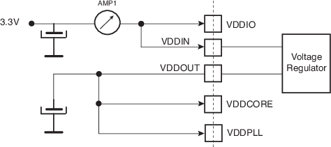
- Current measurement on AMP1 with and without the 1 Kbyte backup SRAM
- Measurements are made at ambient temperature
Figure 1. Measurement Setup
| Total Consumption | Worst Case Value | Unit | ||
|---|---|---|---|---|
| at 25°C | at 85°C | at 105°C | ||
| Conditions | AMP1 | AMP1 | AMP1 | |
| VDDIO = 3.6V | 8.4 | 42 | 64 | µA |
| VDDIO = 3.3V | 8 | 39 | 61 | µA |
| VDDIO = 3.0V | 7.6 | 38 | 59 | µA |
| VDDIO = 2.5V | 5.2 | 37 | 58 | µA |
| VDDIO = 1.7V | 3.8 | 35 | 56 | µA |
| Total Consumption | Worst Case Value | Unit | ||
|---|---|---|---|---|
| at 25°C | at 85°C | at 105°C | ||
| Conditions | AMP1 | AMP1 | AMP1 | |
| VDDIO = 3.6V | 5.1 | 16.4 | 24 | µA |
| VDDIO = 3.3V | 3.7 | 14.8 | 23 | µA |
| VDDIO = 3.0V | 3.4 | 13.2 | 22 | µA |
| VDDIO = 2.5V | 2.7 | 12.8 | 21 | µA |
| VDDIO = 1.7V | 1.3 | 9.6 | 18 | µA |