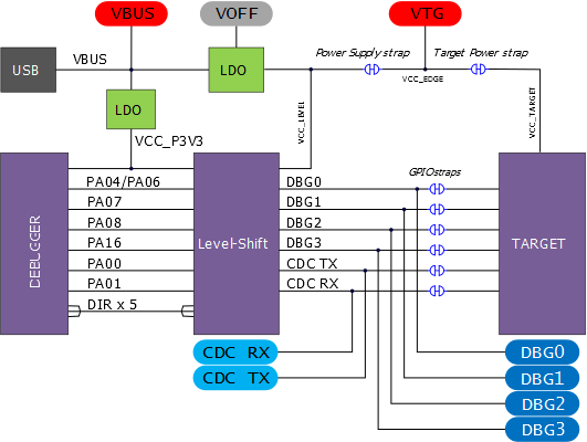
The block diagram below shows all connections between the debugger and the PIC16F15376 microcontroller. The rounded boxes represent connections to the board edge on PIC16F15376 Curiosity Nano. The signal names shown in Figure 1 are printed in silkscreen on the bottom side of the board.
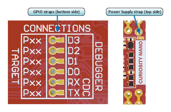
By cutting the GPIO straps with a sharp tool, as shown in Figure 2, all I/Os connected between the debugger and the PIC16F15376 are completely disconnected. To completely disconnect the target regulator and level shifter power from the target, cut the Power Supply strap (J100) as shown in Figure 2.