The implementation of an RTC utilizes the asynchronous operation of the RTC module. In this mode, Timer/Counter0 runs independently from the CPU clock.
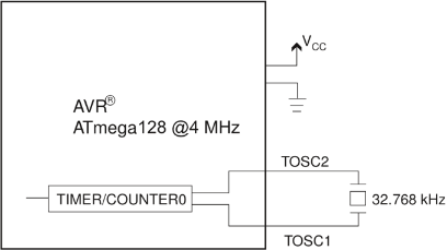
The figure below shows the Atmel AVR Controller operating at 4MHz, from the divided internal calibrated RC-oscillator, when in active mode. When low power operation is desired, the AVR operates in power-down mode, with only the asynchronous timer running from an external 32.768kHz crystal.
The software Real Time Clock (RTC) is implemented using an 8-bit Timer/Counter with overflow interrupts enabled. Each timer overflow interrupt triggers an update of the software variables second, minute, hour, date, month, and year at the correct intervals.
Because the amount of time needed to make the Timer/Counter overflow is constant, each of these timer variables will be incremented by a fixed number, for each timer overflow. This happens in the timer overflow interrupt routine.
To reduce power consumption, the AVR spends most of its time in Power-save mode, in which all on-chip modules are disabled, except for the RTC. As shown in the following table, the MCU typically consumes less than 10µA in this mode. Each timer overflow interrupt will bring the device out of power-save mode, and back into active mode. When in active mode, the timer overflow interrupt routine is executed, before the device re-enters power-save mode.
To calculate the total power consumption, the power consumption in power-save mode should be added to the power consumption in active mode. However, the code executed when the device is awake is expected to be executed in less than 100 clock cycles, keeping the device awake for no more than 25µs (@4MHz). The current consumed in this period can therefore be considered negligible.
According to the above information and the current consumptions listed in the table below, the current consumption can be estimated to be less than 10µA for this application, as opposed to 5mA if the device were not in power-save mode.
| Mode | Typical | Maximum |
|---|---|---|
| Active 4MHz, 3VCC | 5mA | 5.5mA |
| Idle 4MHz, 3VCC | 2mA | 2.5mA |
| Power-down, 3VCC | <1μA | 10μA |
| Power-save, 3VCC | <10μA | - |