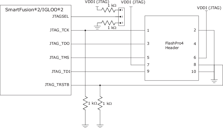
The JTAG interface is used for device programming and testing or for debugging the Arm Cortex-M3 firmware, as listed in the following table. These functions are enabled depending on the state of the JTAGSEL input. When the device reset is asserted, JTAG I/Os are still enabled but cannot be used as the TAP controller in the reset. JTAG I/O are powered by VDDI in the I/O bank where they reside. JTAG pins must be connected as shown in the following figure.
Pin Names |
Direction |
Weak Pull-up |
Description |
|---|---|---|---|
JTAG_TMS |
Input |
Yes |
JTAG test mode select. |
JTAG_TRSTB |
Input |
Yes |
JTAG test reset. Must be held low during device operation. |
JTAG_TDI |
Input |
Yes |
JTAG test data in. |
JTAG_TCK |
Input |
No |
JTAG test clock. Microchip recommends that TCK be tied to VSS or VDDI through a resistor on the board when unused per IEEE® 1532 requirements. This prevents totempole current on the input buffer. |
JTAG_TDO |
Output |
No |
JTAG test data out. |
JTAGSEL |
Input |
Connect the JTAGSEL pin to an external pull-up resistor. The default configuration should enable the FPGA fabric TAP. |
JTAG controller selection. Depending on the state of the JTAGSEL pin, an external JTAG controller connects to either the FPGA fabric TAP (high) or the Arm Cortex-M3 JTAG debug interface (low). For SmartFusion2-based designs, this signal must be held high or low through jumper settings. For IGLOO2-based designs, this signal must be held high through a pull-up resistor. |