- 1.Download the PAT files from the following path in the Microchip website:
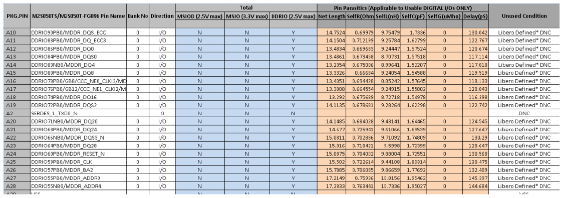
- 2.Open the *Pin_Assignment_Table_Public.xlsx
file.Figure 1. Example PAT Spreadsheet - Initial View
- 3.
Go to the sheet that has the device name.
- 4.
Retain the following columns and delete the remaining columns:
- PGK.PIN
- <Device> Pin Name
-
Direction
- 5.
Insert a row at the beginning of the worksheet. See the following figure.
Figure 2. Example PAT Spreadsheet - Editing Stage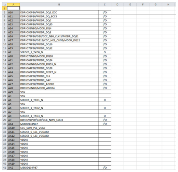
- 6.
Add the following headings for the columns. See Figure 3:
- Number
- Name
-
Type
-
Pin Visibility
-
Shape
-
Pin Group
-
Position
-
Section
For Type, Shape, Position, and Section columns, enter the information manually to avoid warnings from the OrCAD Capture tool.
- 7.
For Type column, choose and type one of the following options:
- Replace I with Input
- Replace O with Output
-
Replace I/O with Bidirectional
Other pin types for the remaining pins:
- 3-State
- Open Collector
-
Open Emitter
-
Passive (Unused pins like DNC or NC)
-
Power (Supply and ground pins)
- 8.
Leave the Pin Visibility column blank. The check boxes are automatically populated in the New Part Creation dialog in the OrCAD Capture tool. See Figure 3.
- 9.
In the Shape column, enter one of the following shapes according to the requirement:
- Clock
- Dot
-
Dot-Clock
-
Line
-
Short Clock
-
Short Dot
-
Short Dot clock
-
Short
-
Zero Length
The default shape for most of the FPGA symbol pins is LINE.
- 10.
Leave the Pin Group column blank.
- 11.
In the Position column, enter one of the following positions according to the requirement:
- Bottom
- Left
-
Right
-
Top
- 12.
In the Section column, enter either a number or an alphabet based on the selection made for the Part Numbering option. OrCAD Capture supports two Part Numbering options, that is 1,2,3,4, and so on., for Numeric option and A, B, C, D, and so on., for Alphabetical option. See Figure 3.
- 13.
Save the Excel file with an appropriate name.
Figure 3. Example PAT Spreadsheet - Final Stage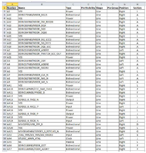
Recommendations for arranging pins in the Section column:
- Arrange individual bank pins in separate sections
- Arrange all power supply pins in one section
- Arrange all ground pins in one section
- All passive pins can be in one section
- Arrange the remaining pins like Clock, JTAG, and SerDes in one section.