- 1.Launch Microsoft Excel, and open the
*.rptfile that has the exported pin information. Before opening, ensure that All Files (*.*) is the file type as shown in the following figure.Figure 1. Importing Pin Names to the Spreadsheet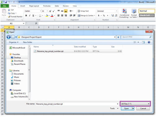
- 2.In the Text Import Wizard - Step 1 dialog, select
Delimited, start import at page 14 and click Next. The
first 14 rows of the spreadsheet have data unrelated to the pin
information.
The following figure shows the Text Import Wizard with the Delimited option selected and the Start Import at Page option having the value 14.
Figure 2. Importing Pin Names to the Spreadsheet — Step 1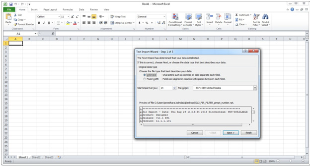
- 3.
In the Text Import Wizard - Step 2 dialog, select the following as Delimiters and click Next:
- Tab
- Space
I as other
Figure 3. Importing Pin Names to the Spreadsheet — Step 2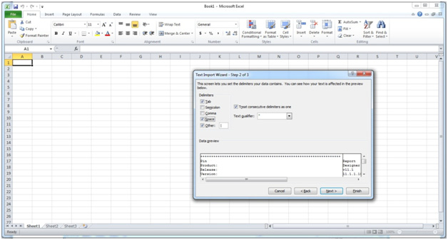
- 4.
Click Finish to import the data in separate columns.
Figure 4. Importing Pin Names to the Spreadsheet — Final Step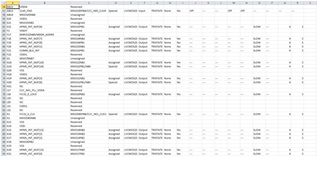
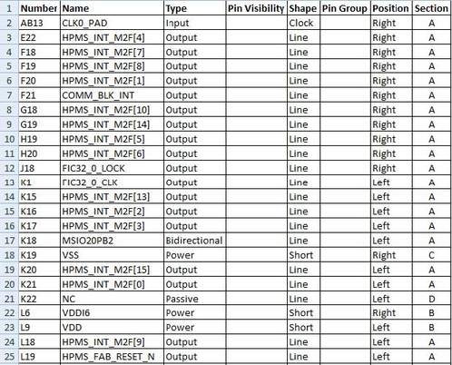
- 5.
Retain the columns A, B, F and delete the remaining columns as they are not required for generating schematic symbols.
Figure 5. Spreadsheet with the Pin Names Imported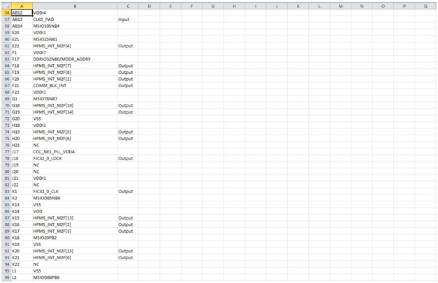
- 6.
Add the following headings for the columns. See Figure 6.
- Number
- Name
Type
Pin Visibility
Shape
Pin Group
Position
Section
By default Number, Name and Type columns are populated from the report. For Type, Shape, Position, and Section columns, add information manually to avoid warnings from the OrCAD Capture tool.
- 7.
For Type column, choose and type one of the following options:
- 3-State
- Bidirectional
Input
Open Collector
Open Emitter
Output
Passive (Unused pins like DNC or NC)
Power (Supply and ground pins)
- 8.
Leave the Pin Visibility column blank. The check boxes are automatically populated in the New Part Creation dialog.
- 9.
In the Shape column, enter one of the following shapes according to the requirement:
- Clock
- Dot
Dot-Clock
Line
Short Clock
Short Dot
Short Dot Clock
Short
Zero Length
The default shape for most of the FPGA symbol pins is the
LINE. - 10.
Leave the Pin Group column blank.
- 11.
In the Position column, enter one of the following positions according to the requirement:
- Bottom
- Left
Right
Top
- 12.
In the Section column, enter either a number or an alphabet based on the selection made for the Part Numbering option. OrCAD Capture supports two Part Numbering options, that is, 1, 2, 3, 4,… for Numeric option and A, B, C, D… for Alphabetical option.
- 13.
Save the Excel file with an appropriate name.
The following figure shows the final pin assignment spreadsheet.