ATtiny817 Xplained Pro has several resistors that can be used to disconnect I/O pins of the ATtiny817 from connectors and on-board ICs and to disconnect power signals.
Info: Note
that some resistors aren't mounted by default on the kit. They are listed in the table
below.
| Designator | Value | Mounted | From | To | Comment |
|---|---|---|---|---|---|
| J100 | cut-strap | N/A | VCC_P3V3 | VCC_P3V3_CM_IN | ATtiny817, peripherals, and connectors power supply |
| R107 | 0R | Yes | U100 OUT | VCC_CM_P3V3 | XAM power supply |
| R108 | 0R | Yes | U100 OUT | VCC_EDBG_P3V3 | EDBG power supply |
| R302 | 10k | Yes | QT BTN1 | PA6 AIN6 | On-board QTouch buttons to the ATtiny817 |
| R305 | 10k | Yes | QT BTN2 | PA7 AIN7 | |
| R307 | 0R | Yes | PB2 UART TXD | PB2 | EDBG CDC and UART on extension headers to the ATtiny817 |
| R308 | 0R | Yes | PB3 UART RXD | PB3 | |
| R309 | 0R | Yes | SW1 | PC5 | Mechanical button SW1 |
| R312 | 0R | No | PB3 TOSC1 | PB3 | 32.768 kHz crystal to the ATtiny817 |
| R313 | 0R | No | PB2 TOSC2 | PB2 | |
| R404 | 0R | Yes | EDBG UPDI | PA0 UDPI RST | Debug interface from the EDBG to the ATtiny817 |
| R406 | 0R | Yes | EDBG CDC RX | PB2 UART TX | EDBG CDC and DGI interfaces to the ATtiny817 |
| R407 | 0R | Yes | EDBG I2C SDA | PA1 I2C SDA | |
| R408 | 0R | Yes | EDBG I2C SCL | PA2 I2C SCL | |
| R414 | 330R | Yes | EDBG CDC TX | PB3 UART RX | |
| R415 | 0R | Yes | EDBG SPI MOSI | PC2 SPI MOSI | |
| R416 | 330R | Yes | EDBG DGI_GPIO0 | PB5 GPIO | |
| R417 | 330R | Yes | EDBG DGI_GPIO1 | PB6 IRQ GPIO | |
| R420 | 330R | Yes | EDBG SPI MISO | PC1 SPI MISO | |
| R425 | 0R | Yes | EDBG SPI SCK | PC0 SPI SCK | |
| R426 | 0R | Yes | EDBG SS | PC4 SPI SS |
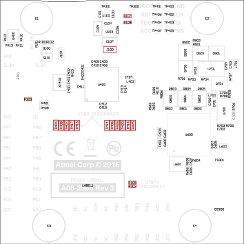
Figure 1. Assembly Drawing, Top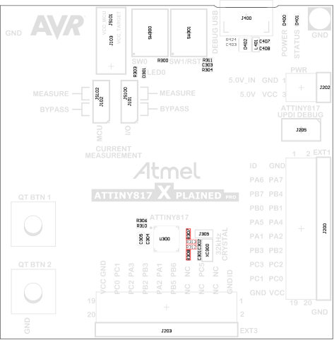
Figure 2. Assembly Drawing, Bottom