Most drivers consist of a mix of code that do not require direct hardware peripheral access and code that require hardware access. In ASF4 this code is split into two different layers called the Hardware Abstraction Layer (HAL) and the Hardware Proxy Layer (HPL). The HAL is the layer where all hardware agnostic code is implemented and the interface that the user access, to use the framework, is defined. The HPL is where the hardware-aware code is implemented.
A typical example of this split is a function that reads a buffer of some length from a hardware module asynchronously. The application does not know when data will arrive at the peripheral so a ring-buffer is used to store the data until the application is ready to read it. As none of the actual hardware implementations of the module supported through this interface has a hardware-based ring-buffer, a software implementation of the buffer is used. Since the data going into the buffer is hardware independent, the ring-buffer is implemented in the HAL driver. Reading the data from the hardware module will, on the other hand, be hardware dependent as the register location, name, and access sequence might differ. This code will, therefore, be implemented in the HPL driver.
The split between HAL and HPL makes it clear which code has to be updated when adding support for new hardware, and which code can be reused without any modification. The expected interface between the HAL and HPL is defined by an abstract device.
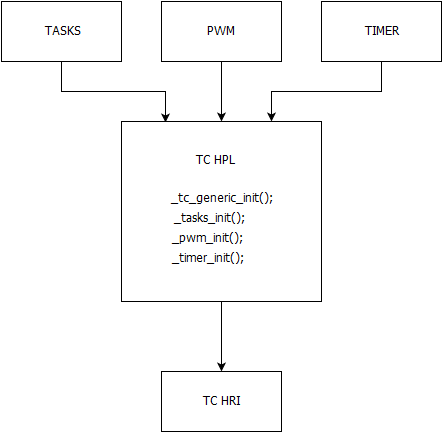
The HPL/HAL driver split allows the different hardware modules with overlapping functionality, to use the same HAL interface. As an example, a device contains different timer/counter module designs: One simple timer/counter design and one more advanced targeted for advanced PWM. Both types can be used to periodically increment a counter and to trigger an interrupt event when the counter reaches some pre-defined value. The same HAL interface and implementation can be used for both module types but mapped to the two different HPL layers.
The abstracted device and interface
The abstracted device is a definition of a non-physical virtual device with a defined feature set. This feature set can be implemented using compatible features in physical hardware modules. This means that an abstract device has a feature set which is a subset of what the physical hardware modules support.
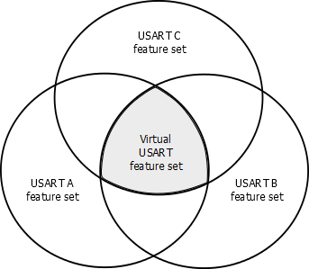
The abstract USART device in the figure above is defined as a subset of what USART A, B, and C can offer. USART implementations often support features like IrDA, SPI-master, Lin, RS485, etc., on top of the USART/UART support, but it is not given which of these features are supported by which implementation. To make sure that the virtual USART device is compatible with the feature set of each physical implementation, the feature scope will be limited to UART/USART. Support for other features can be provided through other abstract device definitions.
The HAL interface gives the user one common interface across multiple hardware implementations. This makes the code easier to port between devices/platforms. Since the HAL implements use cases, the code is more focused, and therefore more optimized for the limited scope than a more general driver would be. Since the HAL driver interfaces hardware through the abstracted device, the HAL driver is completely decoupled from the hardware. The abstract interface is implemented by the hardware’s HPL driver.
Example of abstract device
struct _usart_device {
        struct _usart_callbacks usart_cb;
        void *hw;
};

_usart_init(void *const hw);
_usart_deinit(void *comst hw);
_usart_transmit(void *const hw, uint8_t *const buf, uint32_t length);
This is a simple abstract USART device, with a small interface for init, deinit, and transmit data. If we implement this abstract device for SAM D21 an obvious choice would be to use the SERCOM module to implement this abstract device. To accomplish that, a function to set up the SERCOM and put it into USART mode (init), put data into the data register (transmit), and disable the SERCOM (deinit), must be implemented in the HPL driver for the SERCOM.
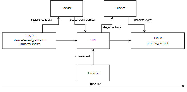
In ASF4, the abstract device is defined as a data container for any data that is shared between the HAL and the HPL implementation. Examples are pointers to hardware registers, buffers, state information, and callback functions for events (interrupts, error detected, etc.). As an example one can use interrupt events. Parts of an interrupt event are processed in the HPL and parts are processed in the HAL like custom callback functions. As earlier noted, the HAL must stay hardware agnostic, so, to be notified that something happens in the underlying hardware, it must register callback functions in the abstract device. This data is shared with the HPL driver, and the HPL driver can use these callbacks to notify the HAL that something has happened in the hardware. This keeps the HAL and the HPL decoupled and there are no dependencies between those two layers, only to the abstract device.