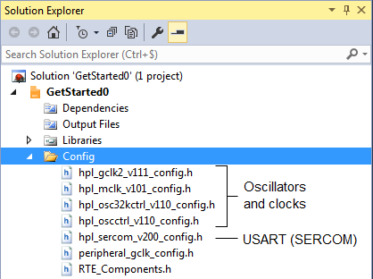
The config folder contains header files, which hold the configuration data associated with each driver. These configuration files are associated with the Hardware Proxy Layer (HPL) of the driver. By connecting the configuration file to the HPL it is possible to expose hardware-specific configuration options to the user, that is, the configuration includes settings which are hardware-aware.
The START-based configuration is based on the ARM-CMSIS wizard annotation format.
As an example, if you open the hpl_oscctrl_vxxx_config.h file, you can check that the only oscillator enabled is the OSC16M:
    // <h> 16MHz Internal Oscillator Control
    // <q> Enable
    // <i> Indicates whether 16MHz Internal Oscillator is enabled or not
    // <id> osc16m_arch_enable
#ifndef CONF_OSC16M_ENABLE
#    define CONF_OSC16M_ENABLE 1
#endif
And that the selected frequency for the OSC16M oscillator is 4 MHz:
	// <y> Oscillator Frequency Selection(Mhz)
    // <OSCCTRL_OSC16MCTRL_FSEL_4_Val"> 4
    // <OSCCTRL_OSC16MCTRL_FSEL_8_Val"> 8
    // <OSCCTRL_OSC16MCTRL_FSEL_12_Val"> 12
    // <OSCCTRL_OSC16MCTRL_FSEL_16_Val"> 16
    // <i> This defines the oscillator frequency (Mhz)
    // <id> osc16m_freq
#ifndef CONF_OSC16M_FSEL
#    define CONF_OSC16M_FSEL OSCCTRL_OSC16MCTRL_FSEL_4_Val
#endif
An extract of the ADC config file (hpl_adc1_v120_config.h) is shown below, representing the ADC conversion resolution configuration output.
    // <o> Conversion Result Resolution
    // <0x0=>12-bit
    // <0x1=>16-bit (averaging must be enabled)
    // <0x2=>10-bit
    // <0x3=>8-bit
    // <i>  Defines the bit resolution for the ADC sample values (RESSEL)
    // <id> adc_resolution
#ifndef CONF_ADC_0_RESSEL
#    define CONF_ADC_0_RESSEL  0x3
#endif
In the #define, the RESSEL is the register bit field name. The value of the define represents what will be written to the associated register. The commented out values function as an enumerator of other potential valid values. Enumerators used in ASF3 have been replaced by this syntax.
Another example is given below, which shows a baud rate calculation of the SERCOM in USART mode, that is the USART use-case of the SERCOM peripheral. Here one can also see the formula in the generated macro in order to calculate the correct value to be programmed into the BAUD register. These calculations will tend to be found near the bottom of the configuration file.
// <o> Baud rate <1-3000000>
// <i> USART baud rate setting
// <id> usart_baud_rate
#ifndef CONF_SERCOM_3_USART_BAUD
#   define CONF_SERCOM_3_USART_BAUD  9600
#endif


//                  gclk_freq - (i2c_scl_freq * 10) - (gclk_freq * i2c_scl_freq * Trise)
// BAUD + BAUDLOW = --------------------------------------------------------------------
//                  i2c_scl_freq
// BAUD:    register value low  [7:0]
// BAUDLOW: register value high [15:8], only used for odd BAUD + BAUDLOW
#define CONF_SERCOM_0_I2CM_BAUD_BAUDLOW (((CONF_GCLK_SERCOM0_CORE_FREQUENCY - \
            (CONF_SERCOM_0_I2CM_BAUD * 10) -\
            (CONF_SERCOM_0_I2CM_TRISE * (CONF_SERCOM_0_I2CM_BAUD / 100) * \
                (CONF_GCLK_SERCOM0_CORE_FREQUENCY / 1000) / 10000 )) * 10 + 5) / \
        (CONF_SERCOM_0_I2CM_BAUD * 10))
#ifndef CONF_SERCOM_0_I2CM_BAUD_RATE
What configuration files will I see?
The configuration files appearing depends on the configuration selected. For example, consider adding Timer and PWM drivers to a SAM D21 project. Both drivers can run on either the TC or TCC peripherals.
If both the Timer and the PWM are configured to run on the TC, then a single conf_tc.h will be placed in the Config folder. However, if the Timer driver runs on the TC while the PWM runs on the TCC, then both the conf_tc.h and the conf_tcc.h will be generated for the Timer and PWM respectively.
Naming convention
What is in the hpl_adc1_v120_config.h file name?
- hpl
- this is the hardware-aware software layer
- adc1_v120(a)
-
adc1 is an ADC project in IC design v120, a silicon version of the ADC integrated peripheral (FYI) (a) variant of the silicon version to support a subset of MCUs.