In order to initialize a register, the user must find the desired configuration of the register to achieve the expected functionality by consulting the device data sheet and setting or clearing register bits, so that the value in the register matches the desired configuration.
Register initialization is most often performed as part of device initialization after
reset, when the register is in a known state of '0'. This is a special
use-case, since:
- The register value may be
0x00 - Various bits and bit fields need to be configured at once
Read-modify-write operations are not needed, when working with bit masks or bit
positions, if the reset value of the register is 0x00 and the register
configures in a single line.
0’, but there are exceptions. For example, the Peripheral
Interrupt Priority Register 3 has several bits with the reset value
‘1’. In this case, the user has to explicitly set the desired
configuration without relying on the fact that usually bits reset values are
0. The reset value for all bits and bit fields in a register are
shown in the figure below.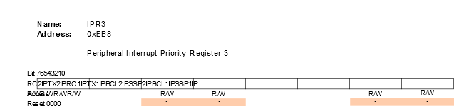
The following example will apply the various methods of configuring a register (T0CON0 – Timer 0 Control Register 0), shown in the figure below.
0’ after reset. 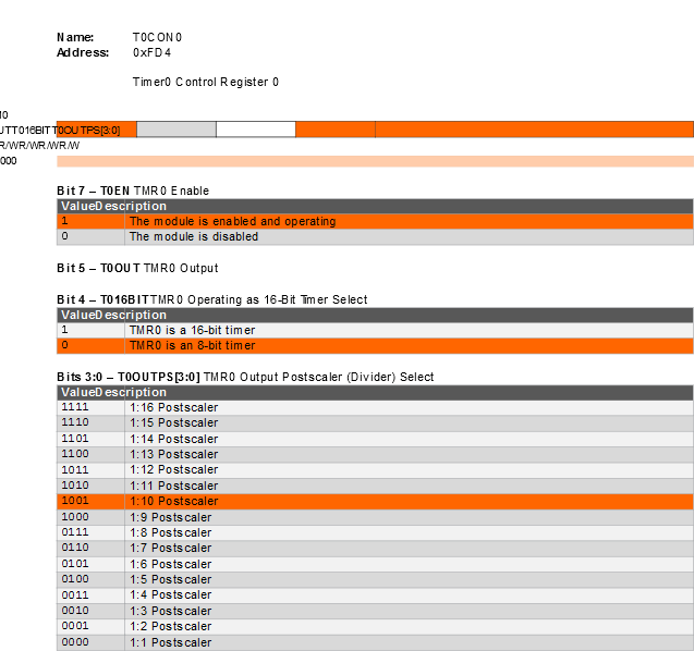
- Enable the timer - T0EN =
1 - Select 8-bit mode - T016BIT =
0(default) - Select a 1:10 postscaler -
T0OUTPS =
1001(changed in 3.3 Change Register Bit Field Configuration to0111)
The resulting value can be directly written to the register:
T0CON0 = 0b1000 1001;    /* binary */
T0CON0 = 0x89;           /* hexadecimal */
T0CON0 = 137;            /* decimal */
However, to improve the readability (and potentially the portability) of the code, it is recommended to use the device defines, which are shown in the upcoming sections.