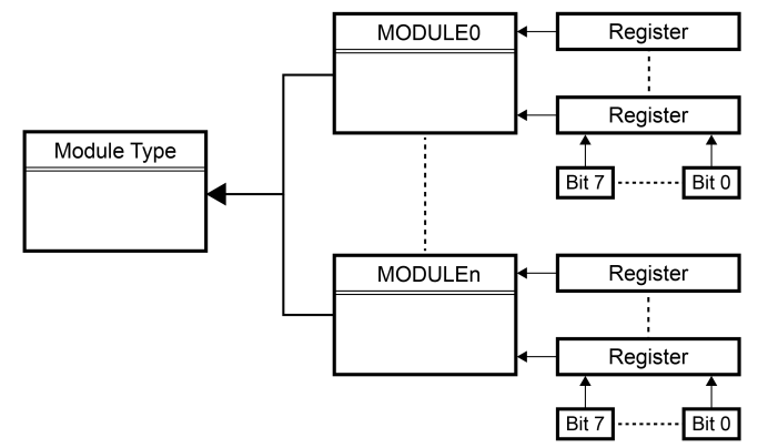
A PIC microcontroller is comprised of several building blocks: a PIC CPU core, SRAM, Flash, EEPROM, and various peripheral modules called module types. Throughout this document, all peripheral modules will be referred to as modules.
Newer PIC families of microcontrollers can have one or more instances of a given module type. All instances of a module have the same features and functions. There can be some modules that are a subset of other module types and inherit some of their features. The inherited features are fully compatible with the respective module type. For example, the subset module for a timer can have fewer compare and capture channels than a full timer module.
A module type can be the Enhanced Universal Synchronous Asynchronous Receiver Transmitter (EUSART), while the module instance is, for example, ‘EUSART1’, where the ‘1’ suffix indicates that the instance is ‘EUSART number 1’. For simplicity, a module instance will be referred to as a module throughout this document, unless there is a need to differentiate.
Each module has several registers that contain control or status bits. All modules of a given type contain the same set or subset of registers. All of these registers contain the same set or subset of control and status bits.
All of the registers corresponding to a module have a fixed address in the I/O memory map. This way, each register will be available at an absolute address specified by the data sheet.
Every module has a dedicated chapter that presents the features of the module, a functional description of the module and the specific signals and guidelines on how to configure a certain mode of operation with all the terminology explained. At the end of a module chapter, the Register Definitions subchapter contains the scope of every register, the reset values of the registers, and whether or not it is readable or writable. It also provides the position of every configurable/accessible bit of a register.
All the registers, their addresses, and the bit names and positions are described in the Register Summary section for each module. The register summary for the ADC module is presented in Figure 1-3.
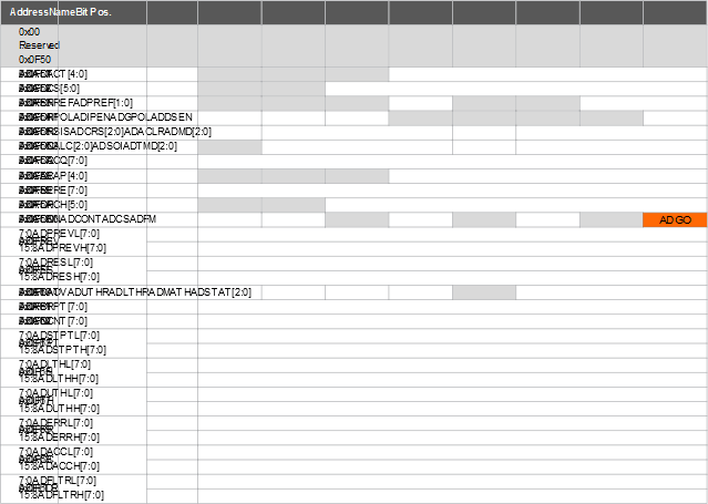
For examples on how to access the ADGO bit from the ADCON0 register, refer to section 2.1.1. Register Unions