The transmission of data from the system to the ATECC608A-TNGTLS is summarized in the table below. The order of transmission is as follows:
- Start Condition
- Device Address Byte
- Word Address Byte
- Optional Data Bytes (1 through N)
- Stop Condition
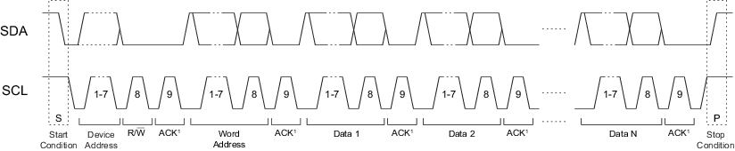
SDA is driven low by ATECC608A-TNGTLS ACK periods.
The following tables label the bytes of the I/O transaction. The column labeled “I2C Name” provides the name of the byte as described in the AT24C16 data sheet.
| Name | I2C Name | Description |
|---|---|---|
| Device Address | Device Address | This byte selects a particular device on the I2C interface. ATECC608A-TNGTLS is selected if bits 1 through 7 of this byte match bits 1 through 7 of the I2C_Address byte in the Configuration zone. Bit 0 of this byte is the standard I2C R/W bit, and should be zero to indicate a write operation (the bytes following the device address travel from the master to the slave). |
| Word Address | Word Address | This byte should have a
value of 0x03 for normal operation. See Section Word Address Values for more information. |
| Command | Data1,N | The command group, consisting of the count, command packet, and the two-byte CRC. The CRC is calculated over the size and packet bytes. See Section I/O Transactions. |
Because the device treats the command input buffer as a FIFO, the input group can be sent to the device in one or many I2C command groups. The first byte sent to the device is the count, so after the device receives that number of bytes, it will ignore any subsequently received bytes until execution is finished.
The system must send a Stop condition after the last command byte to ensure that ATECC608A-TNGTLS will start the computation of the command. Failure to send a Stop condition may eventually result in a loss of synchronization; see Section I2C Synchronization for recovery procedures.