The demo firmware implementation ensures the application operates in either of the below two modes depending upon USB cable connection status and the push buttons SW0 and SW1 state.
- USB mode
- Sensor Node mode
In the USB mode of operation, the sensor node works on USB power. Also, the MCU communicates with the USB host through a USB-UART bridge interface to transmit/receive data.
Whereas in the sensor node mode, the sensor node works on battery power. In this mode, the sensor node joins in a LoRa network and periodically transmit the captured sensors data to The Things Network server through LoRa gateway. Also, in sensor node mode of operation, the ATxmega256A3BU MCU power down mode is enabled to reduce the power consumption.
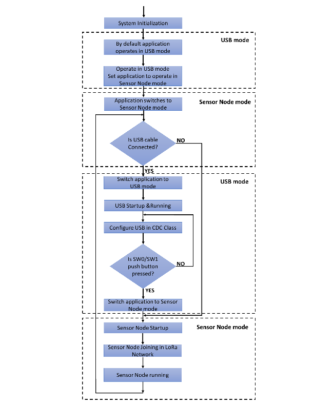
Figure 1 shows a flow diagram of the two different operating modes of sensor node application firmware. After MCU power-up, by default, the application operates in USB mode. From USB mode, the application switches into senor node mode operation. As long as the USB cable is not plugged in, the application operates in the sensor node mode.
If the USB cable is plugged in, the application comes out of sensor node mode and switches to USB mode. In this mode, the USB is configured to operate in CDC class. To an arbitrary push-button (either SW0 or SW1) press event, the application switch back to the sensor node mode, perform the desired operation. Then after, the application checks for the USB connection status. Depending upon the USB cable connection status, the application continues in either of the two operating modes.
The following sub-sections describe the firmware implementation of USB and sensor node modes.