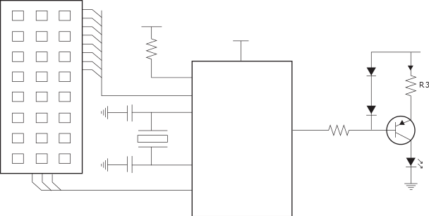
The figure below shows the complete schematics for a remote control transmitter. See the table for component descriptions. The 455kHz resonator gives the application a reliable and flexible clock base. The external LED driver circuit provides a constant current for the IR-LED. Resistor R3 determines the driver strength, and is in this application chosen to 7Ω giving a drive capability of approximately 100mA. Higher resistor values will reduce current, and lowering the resistor value will increase driver strength. The diodes, D1 and D2, are present to ensure a close to constant driving current and to compensate for temperature variations in the transistor.
Figure 1. RC5 Transmitter
| Type | Comment | |
|---|---|---|
| R1 | 3kΩ | External pull-up resistor is present to make the system less susceptible to external noise. Without this component, noise might reset the microcontroller. |
| R2 | 3kΩ |
|
| R3 | 7Ω |
|
| C1 | 100pF | Resonator dependent |
| C2 | 100pF | Resonator dependent |
| D1 | 1N4148 | Small signal diode |
| D2 | 1N4148 | Small signal diode |
| Q1 | BC807-40TD |
|
| XTAL | 455kHz | Resonator |