The assembly code found in the AVR415.ASM file contains the latest RC5 Transmitter software. The program execution can be divided into two routines. Both of them are interrupt driven, and use different Powerdown modes to reduce power consumption. The program is designed to use only one level of hardware stack, leaving two levels for user code.
Main
The main program loop is shown in the figure below. First all registers are initiated. The hardware modulator is configured for correct frequency and duty-cycle. In this application 38kHz is used as the carrier frequency. This differs from the RC5 standard, which specifies 36kHz for the carrier wave. The RC5 signal will, however, be the same, and most standard RC5 Receivers should have no problem receiving and decoding the signal. Once the I/O modules are initialized the purpose of the main loop is to decide what sleep mode to use after the next wake-up.
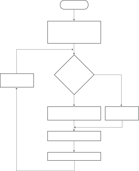
The program execution can roughly be divided into two states; “Transmitting a RC5 code” and “Waiting for a key to be pressed”. While waiting for a key to be pressed, the ATtiny28 is put in Power-down mode. In this mode the current consumption for the device is at a minimum, and the wake-up time is slightly longer than for the Idle mode. Since the wake-up condition is caused by physically pressing a key, the longer wake-up time will not cause a noticeable delay in the system.
Low Level Interrupt
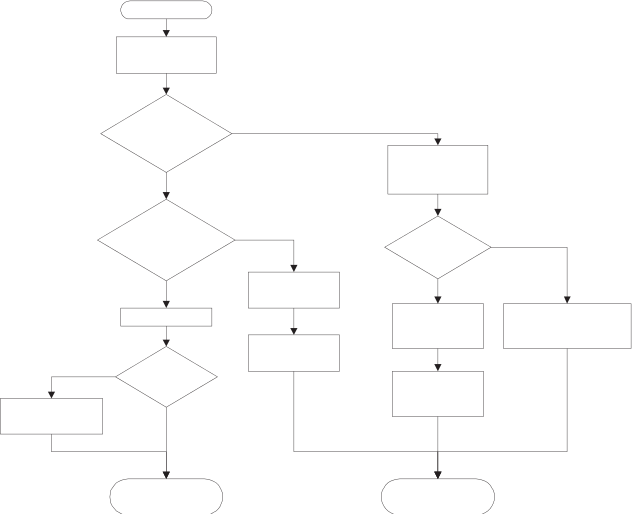
When the ATtiny28 is in Power-down mode, a low level on any of the Port B pins will generate a Low Level interrupt, waking the device and executing the code illustrated by the flowchart in the figure below. The main purpose of this routine is to scan through the keyboard, and determine if a valid key is pressed. If two or more buttons are pressed simultaneously the routine returns the value 0xFF indicating an error. The “checksum” ensures that 63 of 64 combinations of row and column lines are high – that only one unique combination, representing the key, is low. If only one key is pressed, the column and row bit pattern is decoded into a pointer, which is used to perform a look-up in the Command table. Further, the Low Level interrupt also controls the toggling of the control bit, indicating if a new “instance” of a command is present, or if the “same” command should be re-transmitted. At the end of this routine, the hardware modulator is started preparing the transmission.
Timer Interrupt Routine
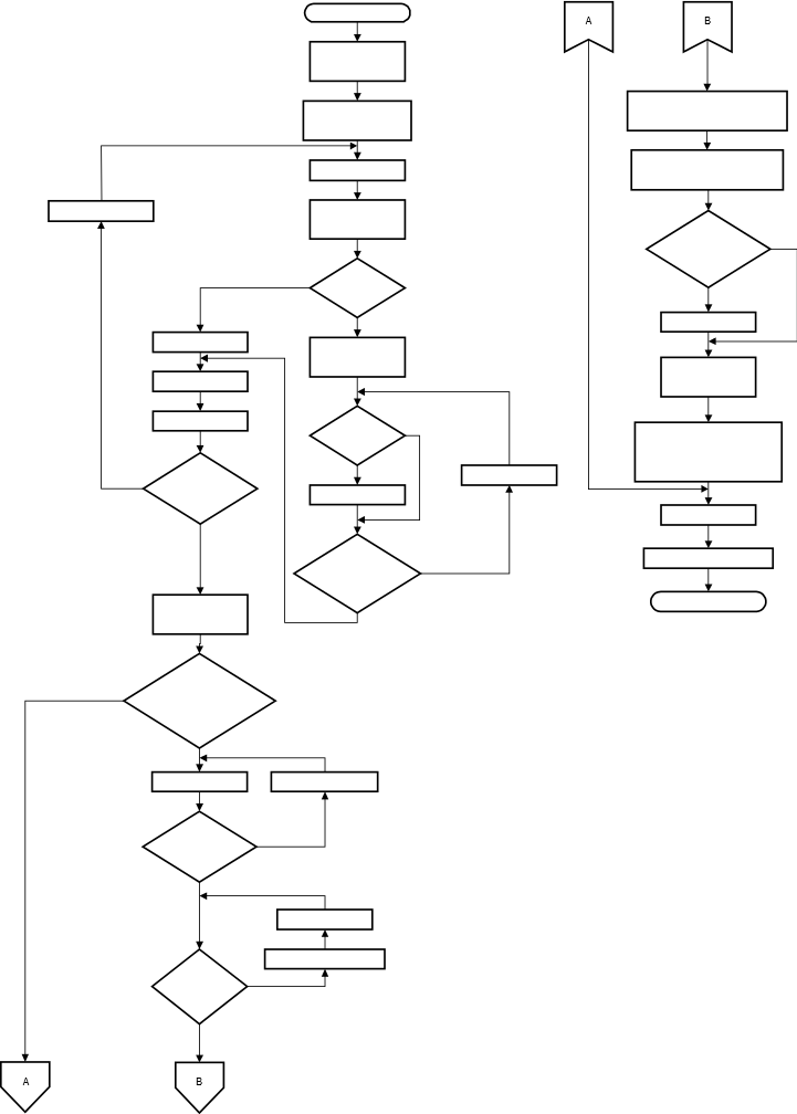
The figure below shows the flowchart for the Timer Overflow interrupt. The main task of the Timer Interrupt routine is to keep track of the bit pattern that will be modulated on the IR LED, i.e., make sure that the transmitted signal is in accordance with the bi-phase coding scheme. Once a complete frame has been transmitted, the routines also generate a necessary delay before a new transmission is to be started.