The AVR Dx devices are equipped with a 10-bit Digital-to-Analog Converter (DAC) that can run up to 140 ksps conversion rate. The output range is between GND and selected voltage reference and can be available on an external pin or to be used by other internal peripherals (like ADC).
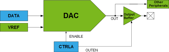
The analog output of the DAC can be connected to a pin by writing a ‘1’
to the Output Buffer Enable (OUTEN) bit in the Control A (DACn.CTRLA) register. The pin
used by the DAC must have the input disabled from the Port peripheral. There is an
output buffer between the DAC output and the pin, which ensures the analog value does
not depend on the load of the pin. The output buffer can only source current, and it has
very limited sinking capability.
The following code snippets show the initialization code for DAC to generate a fixed voltage on the DAC analog output pin:
AVR® Dx - DAC Initialization to Generate Fixed Voltage
/* DAC Value */#define DAC_EXAMPLE_VALUE        (0x258)/* Mask needed to get the 2 LSb for DAC Data Register */#define LSB_MASK                 (0x03)voidDAC0_init(void){
    VREF.DAC0REF = VREF_REFSEL_2V048_gc /* Select the 2.048V Internal Voltage Reference for DAC */| VREF_ALWAYSON_bm;/* Set the Voltage Reference in Always On mode *//* Disable digital input buffer */
    PORTD.PIN6CTRL &=~PORT_ISC_gm;
    PORTD.PIN6CTRL |= PORT_ISC_INPUT_DISABLE_gc;/* Disable pull-up resistor */
    PORTD.PIN6CTRL &=~PORT_PULLUPEN_bm;
    DAC0.CTRLA = DAC_ENABLE_bm          /* Enable DAC */| DAC_OUTEN_bm           /* Enable output buffer */| DAC_RUNSTDBY_bm;/* Enable Run in Standby mode *//* Store the two LSbs in DAC0.DATAL */
    DAC0.DATAL =(DAC_EXAMPLE_VALUE & LSB_MASK)<<6;/* Store the eight MSbs in DAC0.DATAH */
    DAC0.DATAH = DAC_EXAMPLE_VALUE >>2;}