The ADC of AVR Dx devices has a 12-bit resolution and a sample rate of up to 130 ksps. Its multiple internal and external inputs can be used in Single or Differential mode, selectable using the Conversion Mode (CONVM) bit in the Control A (ADCn.CTRLA) register. Unlike the megaAVR devices, in the Differential mode, any combination of available positive and negative inputs is allowed and can be configured using the Multiplexer Selection (MUXPOS and MUXNEG) registers.
The ADC voltage reference is also improved, a dedicated voltage reference
(VREF) being available. This reference is selectable using the ADC0
Reference (ADC0REF) register of the Voltage Reference (VREF) peripheral.
Figure 1. AVR® Dx -
ADC Block Diagram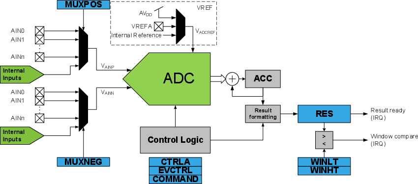
The following code shows the ADC initialization in Single-Ended mode, internal voltage reference:
megaAVR® - ADC Initialization in Single-Ended Mode
voidADC_Init(void){/* Set ADC prescalar to 128 */
   ADCSRA |=(1<< ADPS2)|(1<< ADPS1)|(1<< ADPS0);/* Set ADC reference to 2.56V internal reference */
   ADMUX |=(1<< REFS0);/* Left adjust ADC result to allow easy 8-bit reading */
   ADMUX |=(1<< ADLAR);// No MUX values needed to be changed to use ADC0 input

   ADCSRA |=(1<< ADFR);/* Set ADC to Free-Running mode */
   ADCSRA |=(1<< ADEN);/* Enable ADC */
ADCSRA |=(1<< ADSC);/* Start A2D conversions */}AVR® Dx - ADC Initialization in Single-Ended Mode
voidADC0_init(void){/* Disable digital input buffer */
    PORTD.PIN0CTRL &=~PORT_ISC_gm;
    PORTD.PIN0CTRL |= PORT_ISC_INPUT_DISABLE_gc;/* Disable pull-up resistor */
    PORTD.PIN0CTRL &=~PORT_PULLUPEN_bm;

    ADC0.CTRLC = ADC_PRESC_DIV4_gc     /* CLK_PER divided by 4 */| ADC_REFSEL_INTREF_gc;/* Internal reference */

    ADC0.CTRLA = ADC_ENABLE_bm         /* ADC Enable: enabled */| ADC_RESSEL_12BIT_gc;/* 12-bit mode */

    ADC0.MUXPOS = ADC_MUXPOS_AIN0_gc;/* Select ADC channel 0*/
    ADC0.CTRLA |= ADC_FREERUN_bm;/* Enable Free-Running mode */
    ADC0.COMMAND = ADC_STCONV_bm;/* Start conversion */}