One of the most common reasons for EMC problems with microcontroller products is that the power supply is not good enough. Correct and sufficient decoupling of power lines is crucial for stable microcontroller behavior, and for minimizing the emitted noise from the device.
Looking at the datasheet for an AVR microcontroller, one can be fooled to believe that power supply is not critical. The device has a very wide voltage range, and draws only a few mA supply current. But as with all digital circuits, the supply current is an average value. The current is drawn in very short spikes on the clock edges, and if I/O lines are switching, the spikes will be even higher.
The current pulses on the power supply lines can be several hundred mA if all eight I/O lines of an I/O port changes value at the same time. If the I/O lines are not loaded, the pulse will only be a few ns.
This kind of current spike cannot be delivered over long power supply lines; the main source is (or should be) the decoupling capacitor.
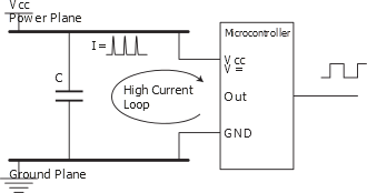
The figure above shows an example of insufficient decoupling. The capacitor is placed too far away from the microcontroller, creating a large high current loop. The power and ground planes here are parts of the high current loop. As a result of this, noise is spread more easily to other devices on the board, and radiated emission from the board is increased even further. The whole ground plane will act as an antenna for the noise, instead of only the high current loop.
This will be the case if the power and ground pins are connected directly to the planes (typical for hole-mounted components) and the decoupling capacitor is connected the same way. The same is often seen for boards with surface-mounted components if the integrated circuits are placed on one side of the board and the decoupling capacitors are placed on the other.

The figure above shows a better placement of the capacitor. The lines that are part of the high current loop are not part of the power or ground planes. This is important, as the power and ground planes otherwise will spread a lot of noise.
The figure below shows another improvement of the decoupling. A series inductor is inserted to reduce the switching noise on the power plane. The series resistance of the inductor must, of course, be low enough to ensure that there will be no significant DC voltage drop.
Generally, the AVR devices where power and ground lines are placed close together (like the AT90S8535) will get better decoupling than devices with industry standard pinout (like the AT90S8515), where the power and ground pins are placed in opposite corners of the DIP package. This disadvantage can be overcome by using the TQFP package, which allows decoupling capacitors to be placed very close to the die. For devices with multiple pairs of power and ground pins, it is essential that every pair of pins get its own decoupling capacitor.
