ESD (electrostatic discharge) is a phenomenon most people have experienced. This is what happens if you feel a small electric shock when you touch your kitchen sink or another grounded object. What happens is that your body has been charged with a small electrostatic charge (easily achieved by walking on synthetic fiber carpets). This charge is released when you touch an object with a different charge or an object connected to ground. For a human being to actually feel the discharge, the voltage must be about 4kV or more, and it is not difficult to achieve tens of kV.
A simple way of modeling this phenomenon is to use a capacitor that will hold the same charge as the body and a series resistor that will release this charge the same way the body does.
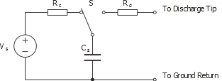
The figure above shows a principle schematic of this setup. CS is the storage capacitor that equals the capacitance of the human body, RD is the discharge resistance that equals the resistance of the human body. VS is a high-voltage power supply, and RC the series resistance of this power supply. When the switch S is connected to RC, the capacitor is charged. When the switch S is connected to RD, the capacitor is discharged through RD and the device under test, which is connected to or placed near the discharge tip. The value of RC is of no practical value for what amount of energy is stored in the capacitor or for how this is transferred to the device under test.
Integrated circuits are usually tested according to MILSTD-883.
Here RC is 1 - 10MΩ, RD is 1.5kΩ, and CS is 100pF. This is the so-called Human Body Model, which tries to emulate the ESD an integrated circuit may experience as a result of manual handling during board production. The traditional test voltage VS a CMOS device is expected to handle is ±2kV. Newer devices like AVR® microcontrollers are often rated to ±4kV or more.
Another model, the Machine Model, tries to emulate the ESD an integrated circuit will experience from automatic handlers. Here CS is twice as big, 200pF. The current limiting resistor RD is zero (!), but an inductor up to 500nH may be inserted instead. RC is 100MΩ. In this model, the rise time of the current is much higher, and most devices fail at voltages higher than ±500V.
ESD compliance according to the EMC directive is based on IEC 1000-4-2. This standard specifies a Human Body model that tries to emulate the ESD a product will experience as a result of normal use. The component values are therefore slightly tougher here than in MIL-STD-883: RC is 100MΩ, RD is 330Ω, and CC is 150pF. This means that a product built by circuits rated at 4kV may not necessarily pass IEC 1000-4-2 at 4kV without adding some kind of external protection.
Another important difference here: MIL-STD-883 only requires that the device is not damaged by the test. The demand of the EMC directive is stronger: the product shall continue to operate as intended, without being disturbed by the ESD pulse. This requirement is tough, as a high-voltage ESD transient on an input pin may easily change the logic value of the pin. This means that the designer of a microcontroller based system must either design hardware to make sure that ESD transient never reaches the I/O pins, or write software that detects and handles such incorrect readings.