If possible, one of the layers should be used as a dedicated ground plane and only that.
If signals are routed in the ground plane, this may interfere with the return paths of the track on the other side. This kind of routing will therefore require detailed analysis of every track on the board, otherwise the whole ground plane may be wasted.
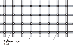
One way of designing a ground plane on a two-layer board and still allow routing on both layers, is to design a ground grid as shown in the figure above. Here every path will have a ground return nearby, creating a relatively small loop. How large the cells and how wide the tracks should be will depend on the application. Higher currents and higher frequencies will require wider tracks and smaller cells.
It is very important to first put the ground grid in place, as it will be very difficult to make room for it after all other tracks have been placed. If required, a segment of the ground grid can be moved to the opposite side of the board to make routing easier or to make room for components. But it is “illegal” to delete segments. If a via or a track has to be moved, put an extra one in the grid to make sure that no cells are larger than the others.
A ground grid is not as good as a complete, unbroken ground plane, but it is better than routing ground just like any other signal.
Another way of designing a similar ground plane is to fill all unused space on both sides of the board and connect the ground planes together with vias wherever needed. It is very important to make sure that the ground plane at every part of the board covers at least one layer and that enough vias are used so the total ground area becomes as complete as possible. This way of creating a ground plane can also be combined with the ground grid described above. Start with a ground grid, then route the rest of the board and fill all unused areas with ground planes. Some of the vias in the ground grid may, in this case, be removed afterwards.
For a mixed signal board with both analog and digital circuits, it is recommended to use an unbroken ground plane for the analog part of the board, as this will provide better noise immunity for sensitive analog circuits.