To generate this project using MPLAB Code Configurator (MCC), follow the next steps:
- 1.Create a new MPLAB X IDE project for PIC18F47Q10.
- 2.Open MCC from the toolbar (more information about how to install the MCC plug-in can be found here).
- 3.Go to Project Resources →
System → System Module and make the following configurations:
- Oscillator Select: HFINTOSC
- HF Internal Clock: 32 MHz
- Clock Divider: 32
- In the Watchdog Timer Enable field, in the WWDT tab, WDT Disabled has to be selected.
- 4.From the Device Resources window, add
TMR1 and do the following configurations:
- Enable Timer: checked
- Timer Clock tab
- Clock Source: FOSC/4
- Prescaler: 1:8
- Enable Gate tab:
checked
- Enable Gate Toggle: checked
- Enable Gate Single-Pulse mode: checked
- Gate Polarity: Low
- Enable Timer Interrupt: Checked
- Enable Timer Gate Interrupt: Checked
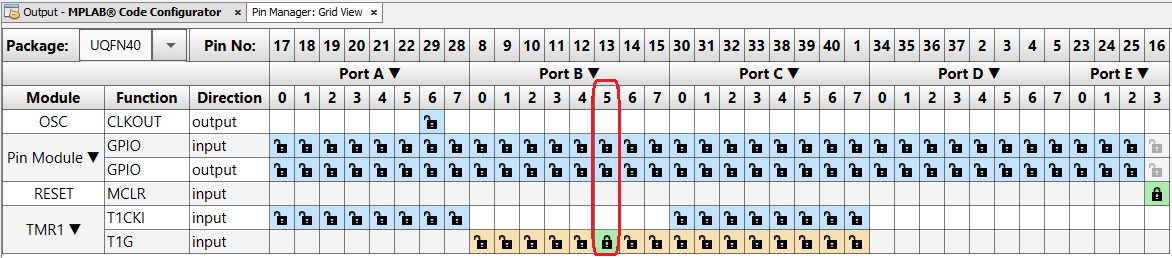
- 5.Open Pin Manager → Grid
View window and select UQFN40 in the MCU package field and
make the following pin configuration to enable the internal signal access to the
I/O:Figure 1. Pin Mapping
- 6.Click Generate in the Project Resources tab.
- 7.For this example, some extra code is required aside from the one generated from
MCC.
- The Global and Peripheral
interrupts need to be enabled in the
main.cfile. The macros were created by the MCC and the user needs to remove the “//” so they are no longer treated as comments:// Enable the Global Interrupts INTERRUPT_GlobalInterruptEnable(); // Enable the Peripheral Interrupts INTERRUPT_PeripheralInterruptEnable(); - In the
tmr1.cfile, theTMR1_ISR()function needs to be updated to stop the gate control because the button was not released yet and it will generate an undesired interrupt when that will happen. It also needs to clear the Interrupt flag, reset the counted value and re-enable the timer gate control for a new acquisition. The following function is used:void TMR1_ISR(void) T1GCON &= ~_T1GCON_T1GGO_MASK; PIR4 &= ~_PIR4_TMR1IF_MASK; PIR5 &= ~_PIR5_TMR1GIF_MASK; TMR1_WriteTimer(0); T1GCON |= _T1GCON_T1GGO_MASK; if(TMR1_InterruptHandler) { TMR1_InterruptHandler(); } } - In the
tmr1.cfile, theTMR1_GATE_ISR()function needs to be updated to clear the Interrupt flag, reset the counted value and re-enable the timer gate control for a new acquisition. The following function is used:void TMR1_GATE_ISR(void) { PIR5 &= ~(_PIR5_TMR1GIF_MASK); TMR1_WriteTimer(0); T1GCON |= _T1GCON_T1GGO_MASK; }
- The Global and Peripheral
interrupts need to be enabled in the