To generate this project using MPLAB Code Configurator (MCC), follow the next steps:
- 1.Create a new MPLAB X IDE project for PIC18F47Q10.
- 2.Open MCC from the toolbar (more information about how to install the MCC plug-in can be found here).
- 3.Go to Project Resources →
System → System Module and make the following configurations:
- Oscillator Select: HFINTOSC
- HF Internal Clock: 32 MHz
- Clock Divider: 1
- In the Watchdog Timer Enable field in the WWDT tab, WDT Disabled has to be selected.
- In the Programming tab, Low-Voltage Programming Enable has to be checked
- 4.From the Device Resources window, add
TMR1 and make the following configurations:
Timer1 Configuration:
- Enable Timer: checked
- Timer Clock tab
- Clock Source: FOSC/4
- Prescaler: 1:8
- Enable Gate tab:
checked
- Enable Gate Toggle: checked
- Enable Gate Single-Pulse mode: checked
- Enable Timer Gate Interrupt: checked
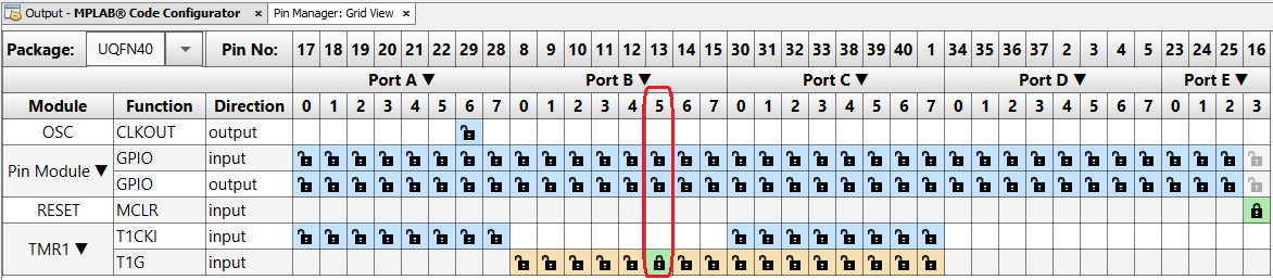
- 5.Open Pin Manager → Grid
View window and select UQFN40 in the MCU package field and
make the following pin configurations to enable the internal signal access to the
I/O:Figure 1. Pin Mapping
- 6.Click Generate in the Project Resources tab.
- 7.For this example, some extra code is required aside from the one generated from
MCC.
- The Global and Peripheral
interrupts need to be enabled in the
main.cfile. The macros were created by the MCC and the user needs to remove the “//” so they are no longer treated as comments:// Enable the Global Interrupts INTERRUPT_GlobalInterruptEnable(); // Enable the Peripheral Interrupts INTERRUPT_PeripheralInterruptEnable(); - In the
tmr1.cfile, theTMR1_GATE_ISR()function needs to be updated to clear the Interrupt flag, read the counted value, reset it afterward and re-enable the timer gate control for a new acquisition. The following configuration is used:void TMR1_GATE_ISR(void) { volatile uint16_t value = 0; PIR5 &= ~(_PIR5_TMR1GIF_MASK); value = TMR1_ReadTimer(); TMR1_WriteTimer(0); T1GCON |= _T1GCON_T1GGO_MASK; }
- The Global and Peripheral
interrupts need to be enabled in the
Note: To obtain the frequency of the measured
signal from the counted value read, the clock source frequency of the timer needs to be
divided by the value.