To generate this project using MPLAB Code Configurator (MCC), follow the next steps:
- 1.Create a new MPLAB X IDE project for PIC18F47Q10.
- 2.Open MCC from the toolbar (more information about how to install the MCC plug-in can be found here).
- 3.Go to Project Resources →
System → System Module and make the following configurations:
- Oscillator Select: HFINTOSC
- HF Internal Clock: 1 MHz
- Clock Divider: 1
- In the Watchdog Timer Enable field in the WWDT tab, WDT Disabled has to be selected
- In the Programming tab, Low-Voltage Programming Enable has to be checked
- 4.From the Device Resources window, add
TMR2, TMR4, ADCC and do the following configurations:
Timer2 Configuration:
- Enable Timer: checked
- Control Mode: Roll over pulse
- Ext. Reset Source: TMR4_postscaled
- Start/Reset Option: Starts at
T2ON =
1and TMR2_ers =0 - Timer Clock tab
- Clock Source: LFINTOSC
- Clock Prescaler: 1:64
- Postscaler: 1:1
- Set 100 ms period in the Timer Period tab
Timer4 Configuration:
- Enable Timer: checked
- Control Mode: Roll over pulse
- Ext. Reset Source: T4INPPS
- Start/Reset Option: Resets at
TMR4_ers =
1 - Timer Clock tab
- Clock Source: LFINTOSC
- Clock Prescaler: 1:64
- Postscaler: 1:1
- Set 500 ms period in the Timer Period tab
- Enable Timer Interrupt: checked
ADCC Configuration:
- Enable ADC: Checked
- Operating: Basic mode
-
- In the ADC
tab, check the following options:
- ADC Clock → Clock Source: Select FRC
- Auto-conversion Trigger: Select TMR2
- CVD Features
tab:
- Enable ADC Interrupt: checked
- In the ADC
tab, check the following options:
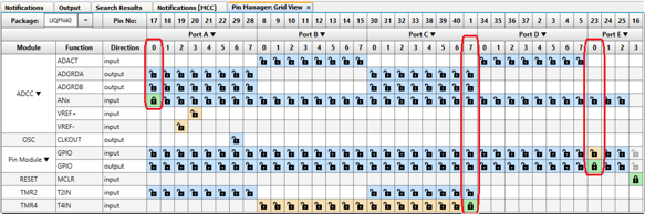
- 5.Open Pin Manager → Grid
View window, select UQFN40 in the MCU package field, and select the
I/O pins outputs to enable the internal signal access to the I/O.Figure 1. Pin Mapping
- 6.Go to Project Resources → Pin Module → RA0(ANA0) and select only the Analog box. For the RC7 pin, select WPU, rename IO_RE0 to LED0 and select Output box .
- 7.Click Generate in the Project Resources tab.
- 8.Add these lines into the
main.cfile:#define DesiredThreshold 300 /* Desired threshold value */ #define MaxThreshold 500 /* Maximum threshold value */ volatile uint16_t adcVal; void TMR4_interrupt(void) { /* HLT trigger: if adcVal > MaxThreshold and pin RC7 pulled-down */ if (adcVal > MaxThreshold) { /* Toggle LED0 at the Timer2Period frequency */ LED0_Toggle(); /* HLT will stop TMR2 that also stops ADCC */ TMR2_Stop(); } } void ADCC_interrupt(void) { /* This will toggle at a rate of 10Hz if adcVal < DesiredThreshold */ if (adcVal < DesiredThreshold) { LED0_Toggle(); } adcVal = ADCC_GetConversionResult(); } void main(void) { // Initialize the device SYSTEM_Initialize(); TMR4_SetInterruptHandler(TMR4_interrupt); ADCC_SetADIInterruptHandler(ADCC_interrupt); // Enable the Global Interrupts INTERRUPT_GlobalInterruptEnable(); // Enable the Peripheral Interrupts INTERRUPT_PeripheralInterruptEnable(); while (1) { if ((adcVal > DesiredThreshold)&&(adcVal < MaxThreshold)) { LED0_SetLow(); } } }