The TWI supports several transmission modes with different frequency limitations:
- Standard mode (Sm) up to 100 kHz
- Fast mode (Fm) up to 400 kHz
- Fast mode Plus (Fm+) up to 1 MHz
The low (tLOW) and high (tHIGH) times are determined by the Host Baud Rate (TWIn.MBAUD) register, while the rise (tR) and fall (tOF) times are determined by the bus topology.
Figure 1. SCL Timing
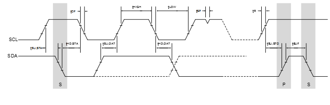
- tLOW is the low period of SCL clock
- tHIGH is the high period of SCL clock
- tR is determined by the bus impedance; for internal pull-ups. Refer to the Electrical Characteristics section for details.
- tOF is the output fall time and is determined by the open-drain current limit and bus impedance. Refer to the Electrical Characteristics section for details.
Properties of the SCL Clock
The SCL frequency is given
by:
f SCL = 1 t LOW + t HIGH + t OF + t R [Hz]
Figure 2. SCL Frequency
The SCL clock is designed to have a 50/50 duty cycle, where the low period of the duty cycle comprises of tOF and tLOW. tHIGH will not start until a high state of SCL has been detected. The BAUD bit field in the TWIn.MBAUD register and the SCL frequency are related by the following formula:
Figure 3. SCL Frequency
Figure 3 can be transformed to express BAUD:
B A U D = f C L K _ P E R 2 × f S C L − ( 5 + f C L K _ P E R × t R 2 )
Figure 4. BAUD
Calculation of the BAUD Value
To ensure operation within the specifications of the desired speed mode
(Sm, Fm, Fm+), follow these steps: