Input Overview
The inputs can be individually:
- Masked
- Driven by Peripherals:
- Analog Comparator (AC) output
- Timer/Counters (TC) waveform outputs
- Driven by Internal Events from Event System
- Driven by Other CCL Submodules
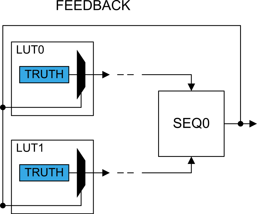
Internal Feedback Inputs (FEEDBACK)
When selected (INSELy = FEEDBACK in CCL.LUTnCTRLx), the Sequencer (SEQ) output is used as input for the corresponding LUT.
The output from an internal sequencer can be used as an input source for the LUT. See the figure below for an example for LUT0 and LUT1. The sequential selection for each LUT follows the formula:
With N representing the sequencer number, and i = 0, 1, 2 representing the LUT input index.
For more details, refer to Sequencer Logic.
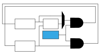
Linked LUT (LINK)
When selecting the LINK input option, the next LUT’s direct output is used as the LUT input. In general, LUT[n+1] is linked to the input of LUT[n]. LUT0 is linked to the input of the last LUT.
Internal Events Inputs Selection (EVENT)
Asynchronous events from the Event System can be used as input to the LUT. Two event input lines (EVENT0 and EVENT1) are available and can be selected as LUT input. Configure the Event System before selecting the EVENT input option.
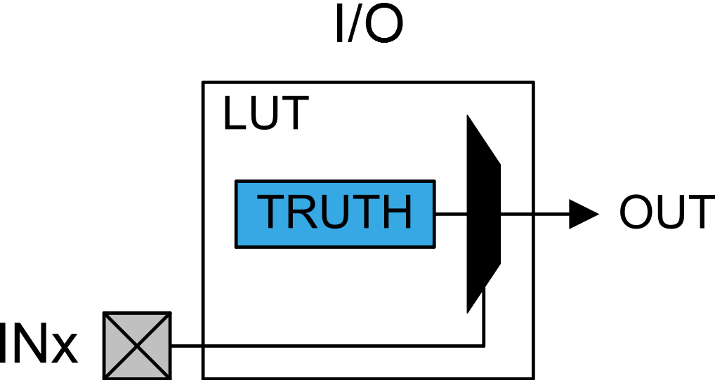
I/O Pin Inputs (I/O)
When selecting the I/O option, the LUT input will be connected to its corresponding I/O pin. Refer to the I/O Multiplexing and Considerations section for more details about where the LUTnINy is located.
Peripherals
- INSEL0 in CCL.LUTnCTRLB
- INSEL1 in CCL.LUTnCTRLB
- INSEL2 in CCL.LUTnCTRLC