The Flash is divided into a set of pages. A page is the basic unit addressed when programming the Flash. It is only possible to write or erase a whole page at a time. One page consists of several words.
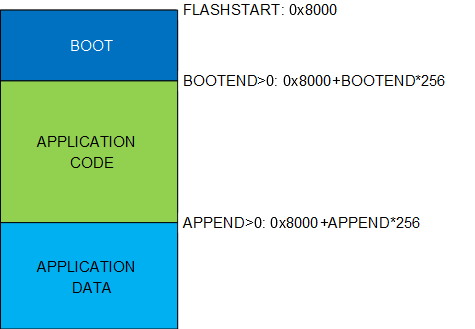
The Flash can be divided into three sections in blocks of 256 bytes for different security. The three different sections are BOOT, Application Code (APPCODE), and Application Data (APPDATA).
Section Sizes
The sizes of these sections are set by the Boot Section End (FUSE.BOOTEND) fuse and the Application Code Section End (FUSE.APPEND) fuse.
The fuses select the section sizes in blocks of 256 bytes. The BOOT section stretches from the start of the Flash until BOOTEND. The APPCODE section runs from BOOTEND until APPEND. The remaining area is the APPDATA section.
| BOOTEND | APPEND | BOOT Section | APPCODE Section | APPDATA Section |
|---|---|---|---|---|
0 |
— |
0 to FLASHEND |
— |
— |
> 0 |
0 |
0 to 256*BOOTEND |
256*BOOTEND to FLASHEND |
— |
> 0 |
≤ BOOTEND |
0 to 256*BOOTEND |
— |
256*BOOTEND to FLASHEND |
> 0 |
> BOOTEND |
0 to 256*BOOTEND |
256*BOOTEND to 256*APPEND |
256*APPEND to FLASHEND |
If BOOTEND is written to ‘0’, the entire Flash is regarded as the BOOT
section. If APPEND is written to ‘0’ and BOOTEND >
0, the APPCODE section runs from BOOTEND to the end of Flash (no APPDATA
section). When APPEND ≤ BOOTEND, the APPCODE section is removed, and
the APPDATA runs from BOOTEND to the end of Flash. When APPEND >
BOOTEND, the APPCODE section spreads from BOOTEND until APPEND. The remaining area is
the APPDATA section.
If there is no boot loader software, it is recommended to use the BOOT section for Application Code.
- 1.After Reset, the default vector table location is at the start of the APPCODE section. The peripheral interrupts can be used in the code running in the BOOT section by relocating the interrupt vector table at the start of this section. That is done by setting the IVSEL bit in the CPUINT.CTRLA register. Refer to the CPUINT section for details.
- 2.If BOOTEND/APPEND, as resulted from BOOTEND and APPEND fuse setting, exceed the device FLASHEND, the corresponding fuse setting is ignored, and the default value is used. Refer to “Fuse” in the Memories section for default values.
Size of Flash Sections
If FUSE.BOOTEND is written to 0x04 and FUSE.APPEND is written to
0x08, the first 4*256 bytes will be BOOT, the next 4*256 bytes will
be APPCODE, and the remaining Flash will be APPDATA.
Inter-Section Write Protection
- The code in the BOOT section can write to APPCODE and APPDATA
- The code in APPCODE can write to APPDATA
- The code in APPDATA cannot write to Flash or EEPROM
Boot Section Lock and Application Code Section Write Protection
Additional to the inter-section write protection, the NVMCTRL provides a security mechanism to avoid unwanted access to the Flash memory sections. Even if the CPU can never write to the BOOT section, a Boot Section Lock (BOOTLOCK) bit in the Control B (NVMCTRL.CTRLB) register is provided to prevent the read and execution of code from the BOOT section. This bit can be set only from the code executed in the BOOT section and has effect only when leaving the BOOT section.
The Application Code Section Write Protection (APCWP) bit in the Control B (NVMCTRL.CTRLB) register can be set to prevent further updates of the APPCODE section.