Power to the AVR128DB48 is connected from the on-board power supply and VTG pin through a 100 mil pin header marked with “POWER” in silkscreen (J101). To measure the power consumption of the AVR128DB48 and other peripherals connected to the board, cut the Target Power strap and connect an ammeter over the strap.
To measure the lowest possible power consumption follow these steps:
- 1.Cut the POWER strap with a sharp tool.
- 2.Solder a 1x2 100 mil pin header in the footprint.
- 3.Connect an ammeter to the pin header.
- 4.Write firmware that:
- 4.1.Tri-states any I/O connected to the on-board debugger.
- 4.2.Sets the microcontroller in its lowest power Sleep state.
- 5.Program the firmware into the AVR128DB48.
Figure 1. Target Power Strap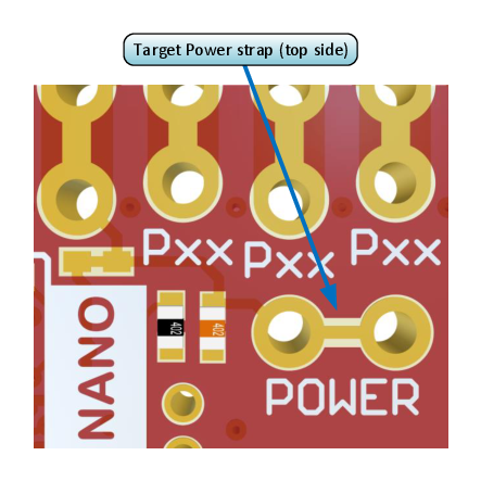
Tip: A 100-mil pin header can be
soldered into the Target Power strap (J101)
footprint for easy connection of an ammeter. Once the ammeter is no longer needed, place
a jumper cap on the pin header.
Info: The
on-board level shifters will draw a small amount of current even when they are not in
use. A maximum of 2 µA can be drawn from each I/O pin connected to a level shifter for a
total of 10 µA. Keep any I/O pin connected to a level shifter in tri-state to prevent
leakage. All I/Os connected to the on-board debugger are listed in On-Board Debugger Connections. To
prevent any leakage to the on-board level shifters, they can be disconnected completely,
as described in Disconnecting the On-board Debugger.