main.c contains a simple program to demonstrate the
demodulator operation. The application uses three Timers available in the AVR for
PWM generation, free running timer and pulsewidth capture. This implementation takes
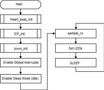
care of considerations mentioned in Application Constraints. The application flow is as follows:
- 1.Initialize the free running timer, Timer 0 as heart beat timer. This is used for generating interrupt approximately, every 1 second to change the duty cycle of PWM waveform generated. In a realtime application where only pulse width capture is needed, this may not be necessary. The Output Compare Register is incremented such that the PWM duty cycle steps through the entire [0:256) range.
- 2.Initialize the ICP module of Timer 1 to capture the pulse width. This is also configured to generate a compare interrupt when there is no edge detected for a duration more than the expected pulse period.
- 3.Initialize the PWM module of Timer 2 to generate and pulse train with constant period and varying duty cycle. In a realtime application where only pulse width capture is needed, this may not be necessary.
- 4.Enable global interrputs and enter sleep mode.
- 5.Periodically get the sampled values and calculate the duty cycle.
- 6.Depending upon the sample values, set the LEDs.
Following flowchart explains the logical flow of
main.c file.
Figure 1. Flowchart for
main()