Being a host device in a synchronous communication interface, the USART in Host SPI mode must generate the interface clock to be shared with the client devices. The interface clock is generated using the fractional Baud Rate Generator, which is described in The Fractional Baud Rate Generator.
Each Data bit is transmitted by pulling the data line high or low for one full clock period. The receiver will sample bits in the middle of the transmitter hold period, as shown in the figure below. It also shows how the timing scheme can be configured using the Inverted I/O Enable (INVEN) bit in the PORTx.PINnCTRL register and the USART Clock Phase (UCPHA) bit in the USARTn.CTRLC register.
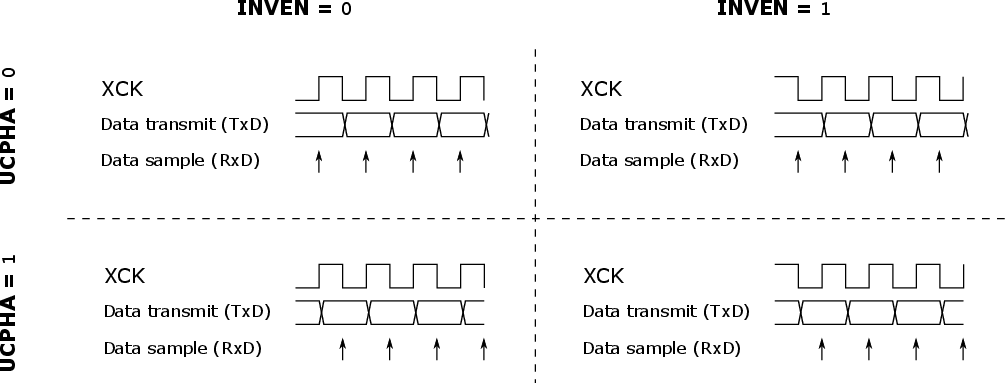
The table below further explains the figure above.
| INVEN | UCPHA | Leading Edge (1) | Trailing Edge (1) |
|---|---|---|---|
| 0 | 0 | Rising, sample | Falling, transmit |
| 0 | 1 | Rising, transmit | Falling, sample |
| 1 | 0 | Falling, sample | Rising, transmit |
| 1 | 1 | Falling, transmit | Rising, sample |
- 1.The leading edge is the first clock edge of a clock cycle. The trailing edge is the last clock edge of a clock cycle.