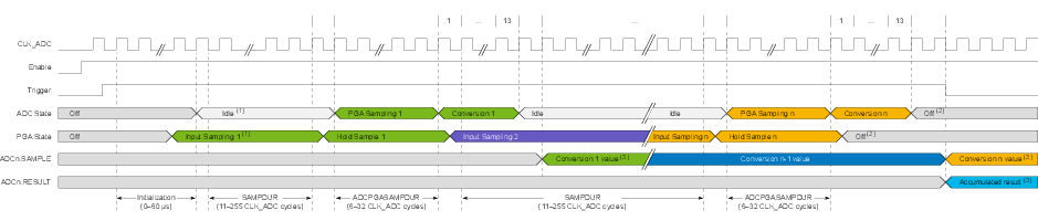
The figure below shows the timing diagram for the ADC when running in Burst Accumulation mode with the PGA.
Figure 1. Timing Diagram - Burst Accumulation with
PGA
Notes:
- 1.The PGA will start sampling the input once the PGA initialization is done, even if the ADC initialization is still ongoing. In this case, the first sampling period will be longer than configured by SAMPDUR.
- 2.If the Low Latency (LOWLAT) bit is set to ‘
1’ in the Control A (ADCn.CTRLA) register, the PGA and the analog modules in the ADC will not turn OFF at the end of the conversion, eliminating the initialization time when triggering the following conversion. The PGA will stay in the Input Sampling state until a new PGA sampling occurs. - 3.The time from the conversion has finished to the outputs are available in the registers is 0.5 CLK_ADC cycles followed by 1 CLK_MAIN cycle. The last conversion and accumulation require an additional CLK_MAIN cycle. With minimum prescaling, this sums up to 1.5 CLK_ADC cycles before the final outputs are available.
The number of samples to accumulate is set by the Sample Number (SAMPNUM) bit field in the Control F (ADCn.CTRLF) register.
For a Burst Accumulation with the PGA, SAMPDUR must be ≥ 11. The total conversion time (tconv), in μs, is calculated by:
The burst conversion rate (fconv) is calculated by: