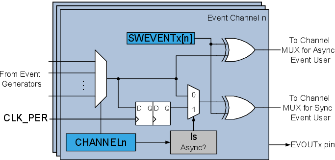
The block diagram shows the operation of an event channel. A multiplexer controlled by Channel n Generator Selection (EVSYS.CHANNELn) register at the input selects which of the event sources to route onto the event channel. Each event channel has two subchannels: one asynchronous and one synchronous. A synchronous user will listen to the synchronous subchannel, and an asynchronous user will listen to the asynchronous subchannel.
An event signal from an asynchronous source will be synchronized by the Event System before being routed to the synchronous subchannel. An asynchronous event signal to be used by a synchronous consumer must last for at least one peripheral clock cycle to ensure that it will propagate through the synchronizer. The synchronizer will delay such an event between two and three clock cycles, depending on when the event occurs.