The assembly code found in AVR410.ASM contains the RC5 decode routine. In addition, it contains an example program which initializes the resources, decodes the RC5 data and outputs the received command on PORTB.
The Detect Subroutine
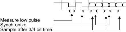
When the detect subroutine is called, it first waits for the data line to be idle high for more than 3.5ms. Then, a start bit can be detected. The length of the low part of the first start bit is measured. If no start bit is detected within 131ms, or if the low pulse is longer than 1.1ms, the routine returns indicating no command received.
The measurement of the start bit is used to calculate two reference times, ref1 and ref2, which are used when sampling the data line. The program uses the edge in the middle of every bit to synchronize the timing. 3/4 of a bit length after this edge, the line is sampled. This is in the middle of the first half of the next bit (see the figure below). The state is stored and the routine waits for the middle edge. Then, the timer is synchronized again and the steps are repeated for the following bits. If the synchronizing edge is not detected within 5/4 bit times from the previous synchronizing edge, this is detected as a fault and the routine terminates. When all the bits are received, the command and system address are stored in the “command” and “system” registers. The control bit is stored in bit 6 of “command”.
| Parameter | Value |
|---|---|
| Code size | 72 words |
| Register usage |
Low registers used: 3 High registers used: 6 Global registers: 6 Pointers used: None |
| Register | Internal | Output |
|---|---|---|
| R1 | "inttemp" - Used by TIM0_OVF | |
| R2 | "ref1" - Holds timing information | |
| R3 | "ref2" - Holds timing information | |
| R16 | "temp" - Temporary Register | |
| R17 | "timerL" - Timing Register | |
| R18 | "timerH" - Timing Register | |
| R19 | "system" - The System Address | |
| R20 | "command" - The Received Command | |
| R21 | "bitcnt" - Counts the bits received |
Timer/Counter 0 Overflow Interrupt Handler
The function of the timer interrupt is to generate a clock base for the timing required. The routine increments the “timerL” Register every 64μs, and the “timerH” every 16.384ms.
| Parameter | Value |
|---|---|
| Code size | 7 words |
| Execution cycles | 6 + reti |
| Register usage |
Low registers used: 2 High registers used: 2 Global registers: 0 Pointers used: None |
| Register | Internal | Output |
|---|---|---|
| R0 | "S" - Temporary Storage of Sreg | |
| R1 | "inttemp" - Used by TIM0_OVF | |
| R17 | "timerL" - Incremented every 64μs | |
| R18 | "timerH" - Incremented every 16.384ms |
Example Program
The example program initializes the ports, sets up the timer, and enables interrupts. Then, the program enters an eternal loop, calling the detect routine. If the system address is correct, the command is output on PORTB.
| Parameter | Value |
|---|---|
| Code size |
79 words - "detect" and "TIM0_OVF" 96 words - Complete example code |
| Register usage |
Low registers: 4 High registers: 6 Pointers: None |
| Interrupt usage | Timer/Counter 0 Overflow Interrupt |
| Peripheral usage |
Timer/Counter 0 Port D, pin 2 Port B (example program only) |