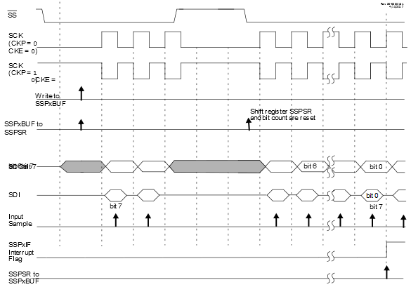
The Client Select can also be used to synchronize communication (see Figure 1). The Client Select line is held high until the host device is ready to communicate. When the Client Select line is pulled low, the client knows that a new transmission is starting.
If the client fails to receive the communication properly, it will be reset at the end of the transmission, when the Client Select line returns to a High state. The client is then ready to receive a new transmission when the Client Select line is pulled low again. If the Client Select line is not used, there is a risk that the client will eventually become out of sync with the host. If the client misses a bit, it will always be one bit off in future transmissions. Use of the Client Select line allows the client and host to align themselves at the beginning of each transmission.
The SS pin allows a
Synchronous Client mode. The SPI must be in Client mode with SS pin control enabled (MSSP Mode Select (SSPM)
bits = 0100).
When the SS pin is low, transmission and reception are enabled and the SDO pin is driven.
When the SS pin goes high, the SDO pin is no longer driven, even if in the middle of a transmitted byte, and becomes a floating output. External pull-up/pull-down resistors may be desirable depending on the application.
When the SPI module resets, the bit counter is forced to
‘0’. This can be done by either forcing the SS pin to a high level or clearing the SSPEN
bit.
- 1.When the SPI is in Client mode with SS pin control enabled (SSPM =
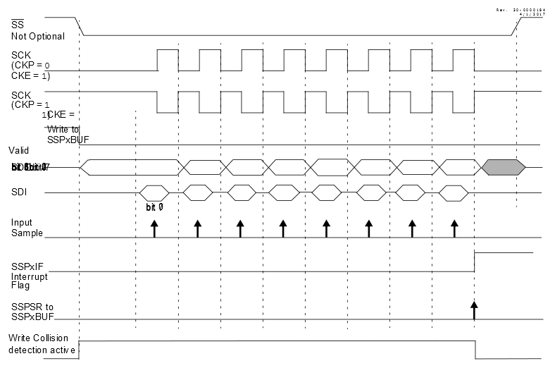
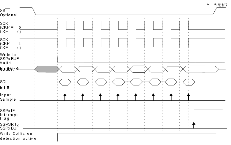
0100), the SPI module will reset if the SS pin is set to VDD. - 2.When the SPI is used in Client mode with CKE set, the user must enable SS pin control (see Figure 3). If CKE is clear, SS pin control is optional (see Figure 2).
- 3.While operated in SPI Client mode, the SMP bit must remain clear.
0)
1)