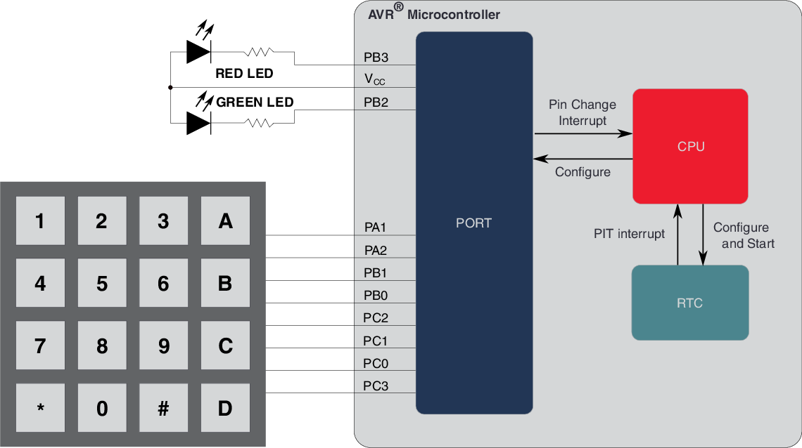
The block diagram below shows an overview of the advanced application example using a 4x4 keypad with the ATtiny1627 Curiosity Nano development board. It shows how the application interacts with the peripherals and CPU of the tinyAVR® 2 device. The keypad and LEDs may be connected to any of the General Purpose Input/Output (GPIO) pins, but in this example, they are connected physically in a row on the ATtiny1627 Curiosity Nano to simplify connection.
Figure 1. Block Diagram