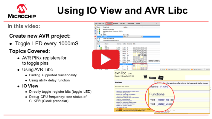
In this video and hands-on training: Building on the training
Create an AVR project in MPLAB X, the LED is now toggled every 1000 mS. In order to do
this, the PINx I/O PORT register is used, as well as a utility delay function from AVR
Libc. Finally, IO View is used to debug the MCU register settings.
- For existing AVR users used to working in Atmel Studio 7, some of the similarities and differences with MPLAB X are emphasized.
- For existing PIC MCU users of MPLAB X, an overview of AVR bare-metal programming references is given (listed below). For each of these references, an attempt is made to show how each one is used in the typical process of writing AVR code.
- ATmega324PB device datasheet
- ATmega324PB device header file
- ATmega324PB Xplained Pro schematic
- AVR Libc: Utility delay function header file
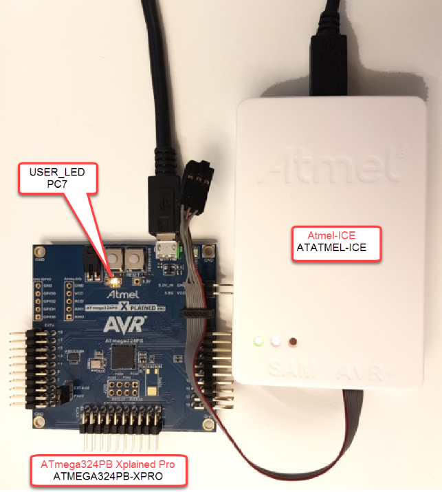
Kit used in this example:
The kit used will be the ATmega324PB Xplained Pro (ATMEGA324PB-XPRO), as well as the Atmel ICE (ATATMEL-ICE) debugger.
- 1.
 Toggling the LED at 1 Hz
The starting point of this training describes how to toggle the LED at a specific time and frequency. Next, a few lines of code are written to toggle the LED every one second.
Toggling the LED at 1 Hz
The starting point of this training describes how to toggle the LED at a specific time and frequency. Next, a few lines of code are written to toggle the LED every one second.- 1.
How can the LED pin (PC7) be toggled?
To answer this question, the Port C Input Pins Address (PINC) register description in the data sheet is consulted.
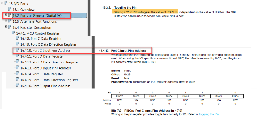 Info: The LED can be toggled by writing a ‘
1’ to PINC7, i.e.PINC = (1<<PINC7); - 2.
Is there a utility delay function available?
AVR Libc functionality is included in the GCC tool-chain and is available to use with the addition of relevant header files. The header files to add can be found by searching the AVR-libc Library Reference for the required functionality.Info: AVR Libc is a Free Software project whose goal is to provide a high-quality C library for use with GCC on AVR microcontrollers. Together, avr-binutils, avr-gcc, and avr-libc form the heart of the Free Software tool-chain for the AVR microcontrollers.
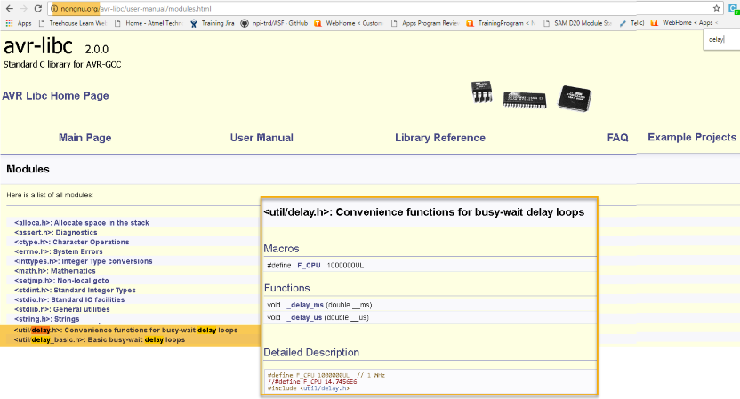
AVR Libc provides a _delay_ms(double_ms) function.
- To use this function, the header file <util/delay> should be included.
- The CPU frequency must be defined (#define F_CPU xxxxxxx -> clock frequency).
- 3.
In order to set F_CPU, what is the default clock frequency of the
ATmega324PB?
Assuming the ATmega324PB is configured at factory defaults, the clock frequency can be found referencing the “System Clock and Clock Options” section of the datasheet, under “Default Clock Source.”
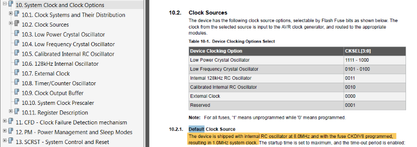 Info: ATmega324PB default clock is 1 MHz: 8 MHz internal RC oscillator, with CKDIV8.
 It should now be possible to add the
required delay function.
It should now be possible to add the
required delay function.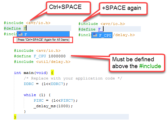
- 1.
How can the LED pin (PC7) be toggled?
- 2.
Verifying Functionality and Debugging
It should now be possible to verify that the LED is blinking at 1Hz. A debug session is started by clicking on the Debug Main Project
 icon.
icon.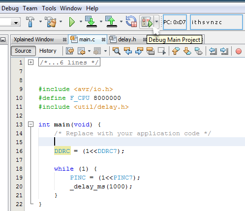
- 1.
If the LED toggling freqency is different than expected, how can the
register settings be verified?
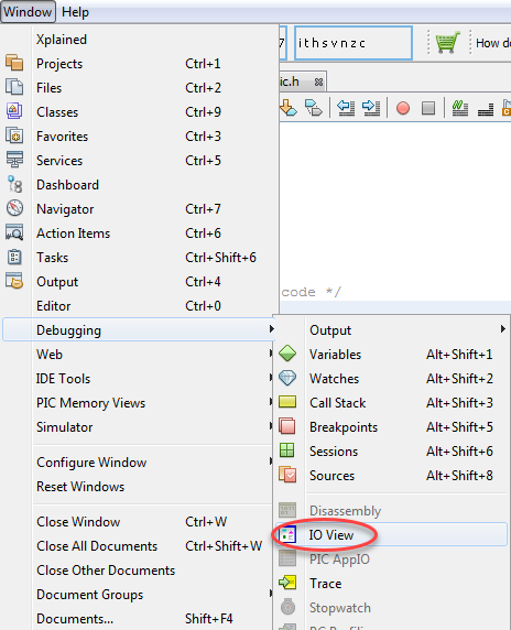
I/O view is a debug window, which can be used to read the current register values, while debugging. It can be found by clicking.Tip: I/O View works the same way in MPLAB X as it does in Atmel Studio.
 In the IO View window the current values
of the Clock Prescaler Enable (CLKPCE) and Clock Prescaler (CLKPS) bits
can be read.
In the IO View window the current values
of the Clock Prescaler Enable (CLKPCE) and Clock Prescaler (CLKPS) bits
can be read.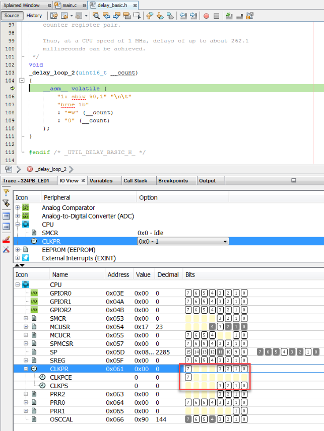 Info:
Info:The Clock Prescaler Enable (CLKPCE) and Clock Prescaler (CLKPS) bits were not set.
So the actual clock frequency was 8 MHz.
Once F_CPU is updated to the real clock frequency, 8 MHz, the LED toggles at the expected frequency.
- 1.
If the LED toggling freqency is different than expected, how can the
register settings be verified?