The main part of the 8-bit Timer/Counter is the programmable counter unit. The following figure shows a block diagram of the counter and its surroundings.
Figure 1. Counter Unit Block Diagram
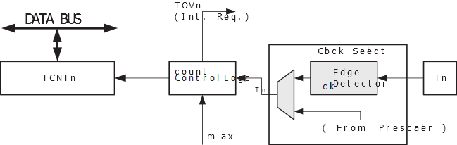
Signal description (internal signals):
The counter is incremented at each timer clock (clkT0). clkT0 can be generated from an external or internal clock source, selected by the clock select bits (CS02:0). When no clock source is selected (CS02:0 = 0) the timer is stopped. However, the TCNT0 value can be accessed by the CPU, regardless of whether clkT0 is present or not. A CPU write overrides (has priority over) all counter clear or count operations.