A serial frame is defined to be one character of data bits with synchronization bits (start and stop bits), and optionally a parity bit for error checking. The USART accepts all 30 combinations of the following as valid frame formats:
- 1 start bit
- 5, 6, 7, 8, or 9 data bits
- no, even or odd parity bit
- 1 or 2 stop bits
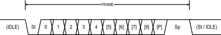
A frame starts with the start bit followed by the least significant data bit. Then the next data bits, up to a total of nine, are succeeding, ending with the most significant bit. If enabled, the parity bit is inserted after the data bits, before the stop bits. When a complete frame is transmitted, it can be directly followed by a new frame, or the communication line can be set to an idle (high) state. The figure below illustrates the possible combinations of the frame formats. Bits inside brackets are optional.
The frame format used by the USART is set by the UCSZ2:0, UPM1:0 and USBS bits in UCSRB and UCSRC. The Receiver and Transmitter use the same setting. Note that changing the setting of any of these bits will corrupt all ongoing communication for both the Receiver and Transmitter.
The USART Character Size (UCSZ2:0) bits select the number of data bits in the frame. The USART Parity mode (UPM1:0) bits enable and set the type of parity bit. The selection between one or two stop bits is done by the USART Stop Bit Select (USBS) bit. The Receiver ignores the second stop bit. An FE (Frame Error) will therefore only be detected in the cases where the first stop bit is zero