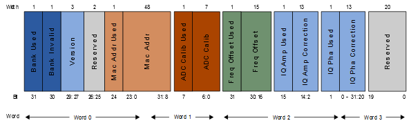
The ATWINC15x0-MR210xB modules have 768 bits of nonvolatile eFuse memory that can be read by the CPU after device reset. The eFuse is partitioned into six 128-bit banks (Bank 0 – Bank 5). Each bank has the same bit map (see the following figure). The purpose of the first 108 bits in each bank is fixed and the remaining 20 bits are general-purpose software-dependent bits or reserved for future use.
- MAC address
- Calibration information (crystal frequency offset and so on)
- Other software-specific configuration parameters
- 1.Invalidate the contents of Bank 2 by programming the Bank Invalid bit field of Bank 2.
- 2.Program Bank 3 with the new MAC address along with the values of ADC Calib (if used in Bank 2), Frequency Offset (from Bank 2), IQ Amp Correction (from Bank 2) and IQ Pha Correction (from Bank 2). The Used bit field for each corresponding value bit field should also be programmed.
- 3.Validate the contents of Bank 3 by programming the Bank Used bit field of Bank 3.
Each bit field (i.e., MAC Address, ADC Calibration, Frequency Offset, IQ Amp Correction and
IQ Pha Correction) has its corresponding Used bit field. Each Used bit field indicates the
firmware that the value in the related bit field is valid. A value of ‘0’
in the Used bit field indicates that the following bit field is invalid and a value of
‘1’ programmed to the Used bit field indicates that the corresponding
bit field is valid and can be used by firmware. By default, ATWINC15x0-MR210xB modules are programmed with the MAC address, Frequency Offset
bits, IQ Amp and IQ Phase fields of Bank 2.
The matrix table below provides details on how different versions of the firmware would handle the IQ Amp used, IQ Amp correction, IQ Pha used and IQ Pha correction bit fields during Initialization.
| Firmware Version Used by Customer | IQ Amp Used and IQ Pha Used Bit Status | |
|---|---|---|
| Device with IQ Amp Used and IQ Pha Used Bits with Value ‘1’ | Device with IQ Amp Used and IQ Pha Used Bits with Value ‘0’ | |
| 19.7 or later for ATWINC15x0 | Firmware loads the IQ cal values from the IQ Amp correction and IQ Pha correction bit fields of corresponding eFuse bank and proceeds with Initialization. | Firmware ignores the values in the IQ Amp correction and IQ pha correction bit fields of corresponding eFuse bank and proceeds with initialization. |
| Prior to 19.7 for ATWINC15x0 | Firmware does not check for the IQ Amp and IQ Pha used bit fields and proceeds with Initialization. | |