Figure 1. SPI Application Schematic(1, 2,
3)
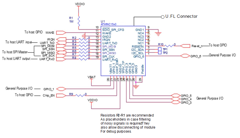
Notes:
- 1.Add 10 uF and 0.01 uF decoupling capacitors very close to pin 24 (1P3V_TP) and GND.
- 2. U.FL connector feature is available only in the ATWINC15x0-MR210xB variant.
- 3.Add test points for pins 2, 3, 18 and 19.