When connecting the PIR sensor, as shown in the figure above, the DC bias will be applied to both the positive and the negative input of the ADC. Since the ADC is configured in differential mode, the DC bias is eliminated, and the full ADC range will be available for the AC signal.
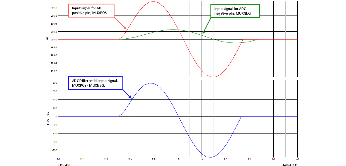
By using the MPLAB® Mindi™ Analog Simulator, it is possible to simulate the behavior of the two low-pass filters when a simulated PIR signal is applied. The simulation also shows how the differential signal to the ADC will look like after the DC bias voltage is removed by the ADC differential inputs.
The PIR signal is simulated using a 1 Hz sine wave with 1 mV amplitude placed at an 800 mV bias voltage.
The two low-pass filters, in combination with the ADC differential input, effectively form a bandpass filter. The figure below shows an MPLAB® Mindi™ simulation of the frequency response of the two filters in combination with the differential ADC.

More information about MPLAB® Mindi™ Analog Simulator, how to download and to use it can be found here: www.microchip.com/mplab/mplab-mindi.