After a battery is inserted in the P4 board, the software starts by performing general initialization. The ports and peripherals required by the application are set up. As a simple start-up test, each red LED is turned ON for 50 milliseconds, and the piezoelectric buzzer is driven with a 4 kHz signal for five milliseconds to produce a short chirp.
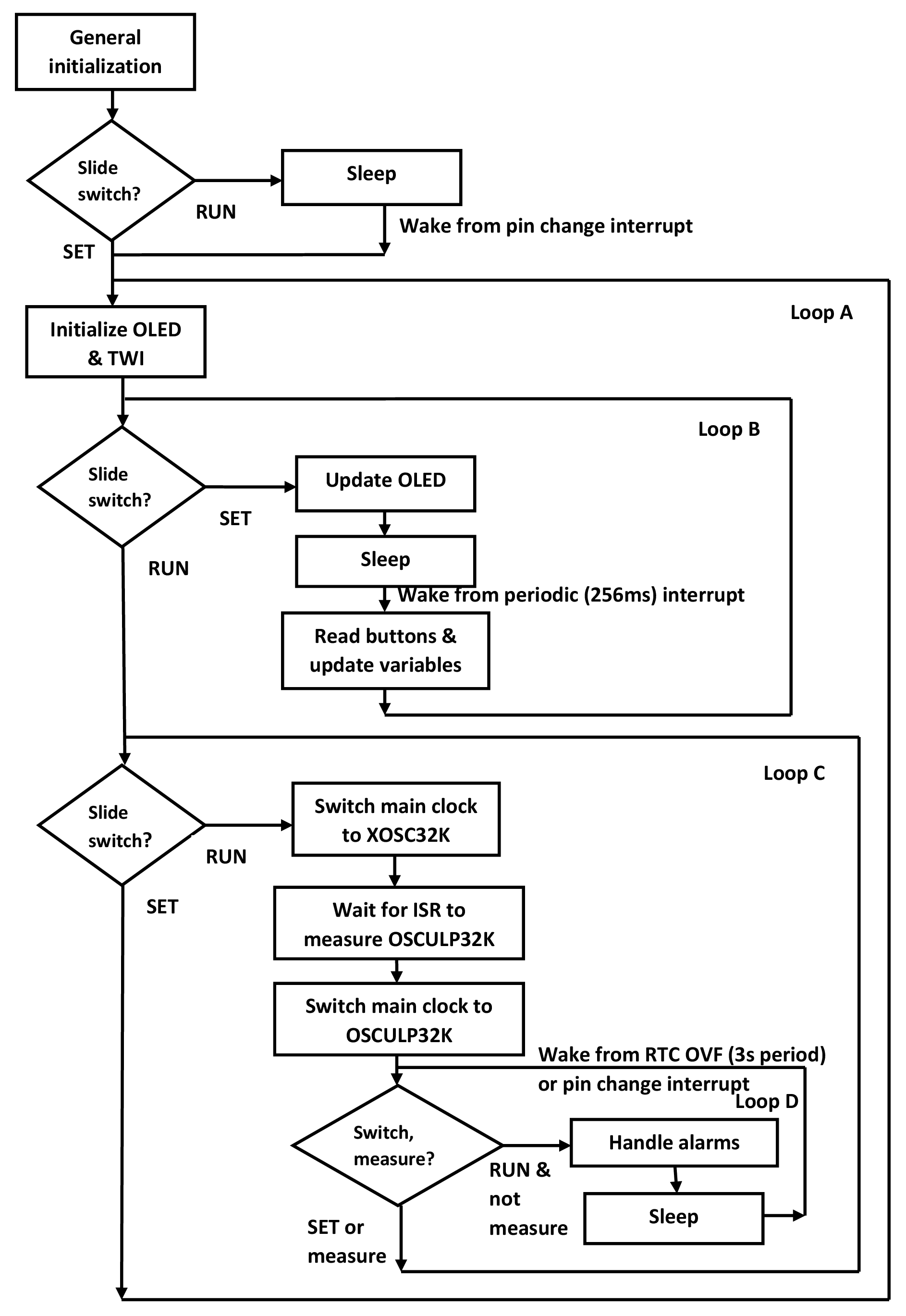
Next, the slide switch on the P4 board is checked to determine if it is in the RUN or SET position. If the switch is in the RUN position, the device goes into STANDBY Sleep mode until it is awakened by a pin change interrupt. Once the switch is in the SET position, the CPU enters a forever loop (Loop A on the flowchart) that starts with the initialization of the OLED and Two-Wire Interface (TWI). The TWI is used for sending data to the OLED.
After the OLED and TWI have been initialized, the software enters a loop (Loop B on the flowchart) that starts by checking the position of the slide switch. If the slide switch is in the RUN position, the code escapes the loop and continues to another section of code. On the other hand, if the slide switch is in the SET position, the software stays in Loop B. This loop is responsible for implementing the alarm/time setting interface using the OLED display and four push buttons.
Loop B updates the OLED display based on several variables that store the alarm settings, current time, etc. All variables are in Static Random-Access Memory (SRAM). The device then goes to Sleep until it is awakened by a periodic interrupt with a period of 256 milliseconds. After the interrupt, the push buttons are read and alarm/time variables are updated accordingly, then program flow proceeds back to the beginning of Loop B.
When Loop B is exited, Loop C is entered. Loop C starts by checking the position of the slide switch. If the slide switch is in the SET position, the code escapes the loop and continues back to the beginning of Loop A. On the other hand, if the slide switch is in the RUN position, the software stays in Loop C.
Loop C is responsible for keeping track of time. It is also responsible for handling alarms by turning them ON or OFF at appropriate times. It starts by switching the main clock to the external 32.768 kHz crystal oscillator (XOSC32K). An interrupt service routine uses XOSC32K and the Timer Counter B peripheral (TCB) to precisely measure the frequency of the internal ultra-low-power 32 kHz oscillator (OSCULP32K). This is a method of calibrating the OSCULP32K so that it can be used for keeping track of time without the additional power consumption of the XOSC32K. After the measurement is completed, the main clock is switched back to OSCULP32K and XOSC32K is disabled.
Next, the RUN/SET switch is checked and the measure variable is checked. (The measure variable is updated in an interrupt service routine so that a new oscillator measurement is triggered every 15 minutes.) If the slide switch is still in the RUN position and it is not time for another oscillator measurement, alarms are checked and handled. Then the device is put into STANDBY Sleep mode.
When the device is awakened, either by a periodic (three seconds) Real-Time Counter (RTC) interrupt or pin change interrupt, the flow returns to the top of Loop D where the slide switch and measure variable are checked. If the slide switch is in the SET position or the measure variable indicates that another oscillator measurement is needed, the flow returns to the top of Loop C. Otherwise, the flow remains in Loop D.
Power consumption is minimized in the software by keeping the device in STANDBY Sleep mode most of the time, with only the OSCULP32K running to clock the RTC. The device only has to leave Sleep mode for a short interval every three seconds to handle the RTC interrupt, and it also has to leave Sleep mode every 15 minutes to perform a new measurement of the OSCULP32K frequency. The XOSC32K only runs for a few seconds every 15 minutes in order to perform the frequency measurement – otherwise, it is disabled and does not consume power. In hardware, the P4 board minimizes power consumption by disconnecting power from the OLED display when the slide switch is in the RUN position.
Because all variables are stored in SRAM, no alarm settings are retained when the battery is removed or depleted.